After nearly a decade I realized that many readers didn’t quite catch how to interpret this blog, seemingly not updated for a long time. They lose interest to read it and to follow the latest updates (the blog is constantly updated). Nine years ago I had intended to design this blog as a sort of diary, “a book” with chapters and paragraphs, going against the conception of modern blog design that sees updates at the top of the timeline. I know, this might sound silly and outdated. Anyway, I am an old-fashioned guy, a technology caveman and this blog fully reflects myself. It is divided into chaptersdealing with the main components of the submarine (weapons, conning tower, hull etc), aftermarket, tools and hopefully in the future, modelling techniques. Each chapter is made of one or more paragraphs with each paragraph added in order of increasing: the updates for each chapter are always edited and not written as a new post and therefore appear at the bottom of the chapter. Each paragraph’s title states the time/date when the update occurred. If you’re interested in one topic/chapter my advice is to read it from top to bottom: you’ll always find the latest update at the bottom. If you are looking for updates only, just select the chapter and scroll down to the bottom.
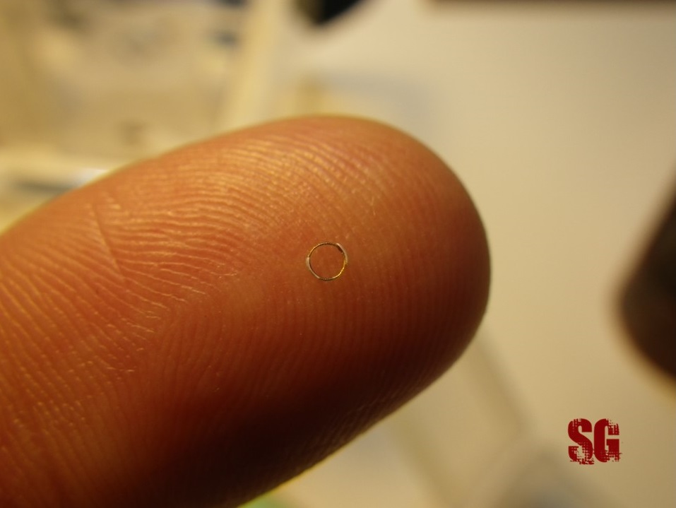
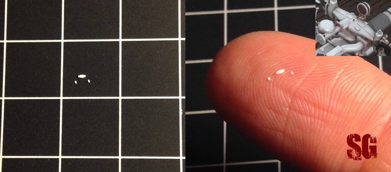
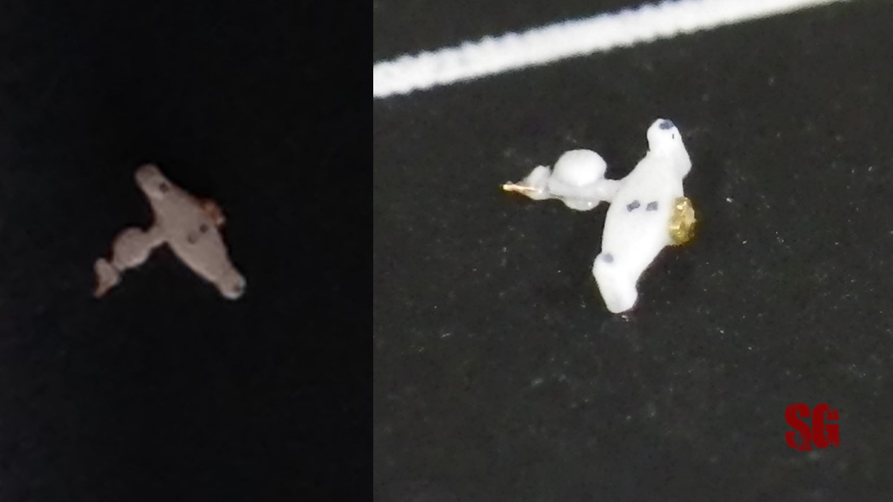
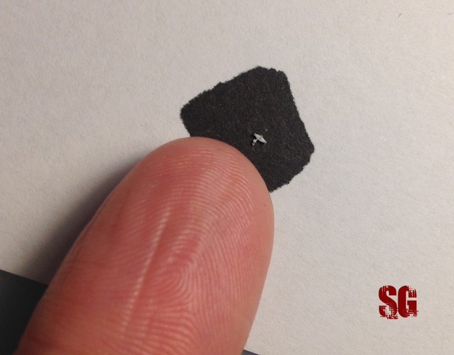
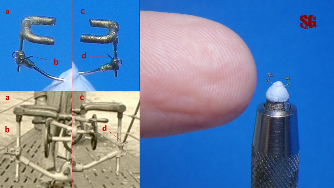
I am still very far from the finishing phase of my project but i’ve already been thinking of a decal representing U 48 emblem. It’s my idea to build the U-boat model as U 48 looked like when she sported the lateral air trunks on her tower sides, thus under the command of Rosing or Bleichrodt. After Bleichrodt won the knight’s cross the cat too was awarded a knight’s cross but until then the emblem sported no crosses (window). After checking the amazing U-boat decals on the Accurate Model Parts site (http://amp.rokket.biz/decals.shtml), I wondered if I could have one custom-made for my project. I asked Dougie Martindale at AMP about the feasibility of my request (they are not set up to do custom decals for customers) and I was lucky enough that I happened to ask for a decal at the right time, when they had space left on a decal sheet they were about to produce. I am very grateful to Dougie for accepting the exceptional request and I congratulate with him for his top notch skills in research and design. The 8 decals (this is what I call generosity!) are very small, some 2 mm-big each and of course most of the details aren’t visible (by the way consider that my bare hand wouldn’t be up to the task of drawing such a small emblem). I am sure that I can field-modify the decals to some extent (by overpainting and chiseling) at the proper time to further improve their already excellent look. Their number is a safety margin for me to get an optimal result. Here they are:
Decals: take two (June 2020)
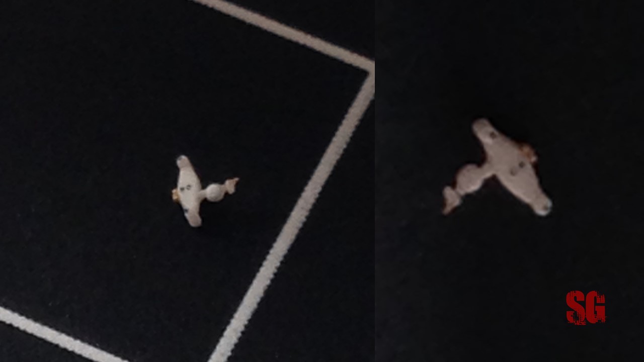
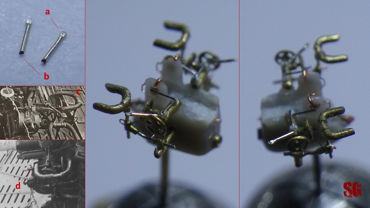
Have I ever told you about Marek Targowicz? He’s a very talented and resourceful polish modeller whose models i’ve been admiring over the years. His legendary 1/400 U 60 model (http://www.shipmodels.info/mws_forum/viewtopic.php?f=60&t=69530) inspired me to finally start this project years ago, and it’s been a constant inspiration through the years. Turns out that Marek starts his own enterprise called Shelf Oddity (http://www.shelfoddity.com), which I dig. Turns out that Marek becomes a friend of mine whom I constantly submit my modelling progress and turn to for advice. Turns out that he offers to create some arching cat decals for me. Now the good thing of this doomed project of mine is that it takes like forever to be completed. “Years disappear like the bubbles in my beer” to quote Neil Hannon but, on the contrary technology constantly improves and advances of printer technology allow for a better printout resolution. So Marek too throws himself into what the Outstanding Dougie Martindale had done to help me 5 years ago: research, design, printout. But most of all he looked after a friend, just like Dougie has done with me over the years. This is what makes modelling something more than just a hobby. The combined result of Marek’s work and improved technology is astonishing, as you may see for yourself:
Marek designed the arching cat in three different formats for me to choose the most appropriate one according to the final conning tower dimensions. Also, he informed me that the white dots you can see in the printouts he tested (without prior lacquering of the surface where the decals were tested nor application of any varnish on top of them), are the result of stochastic ink dots placement by the printer algorithm. I think I can overpaint or chisel them if they stick out like a sore thumb but I don’t think it will be necessary, they will be probably invisible to the naked eye once placed on the grey turret. It’s probably like I can further improve the already smashing look of the insignias with a certain amount of details overpainting. We’ll see. Too early to say now.
Anyway: Thank you Marek. Thank you Dougie. You are two outstanding gentlemen. And generous friends.
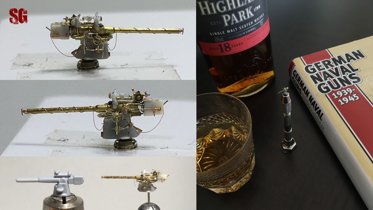
This small vise by Uschi van der Rosten is one of the best tools I’ve ever purchased. Stainless steel, allows to cut and refine styrene sheets, rods and tubing both with a 90° and a 45° angulation. I’m currently using it to shape, carve and drill the gun’s breech (which you can see tightly held in the jigster’s arms in the above picture). Now that I have it, I don’t know what would I do without it. Bravo Uschi!
Uschi Drill Set
Another great piece of hardware produced by Uschi van der Rosten is the Pin Vise Spring Drill. I purchased it together with a set of drill bits ranging from 0.2 to 0.4 mm. The spring-actioned pin vise makes it very easy to drill small caliber holes quickly and effectively. Until now I have routinely drilled very small holes with the help of field-modified drill bits to limit the risk of breaking the bits’ ends (I basically glue the bits into a section of brass tubing which i use as a pin vise), but I found that the manipulation of the thinner bits is not optimal due to their small caliber. I pleasantly discovered that Uschi drill bits can also be easily handled without the Pin Vise Spring Drill since their proximal end is sufficiently wide to allow a good manipulation. I think I am going to embrace the innovation and not going back to my field-modified drill bits!
These files are made of a very flexible stainless steel and can be manipulated by the fingers to drill very small holes (down to 0.06, 0.08, 0,1 mm caliber!) without breaking, but also to carve and file very narrow crevices. Their main advantage, beside the small calibers available, is that they very seldom break and due to their flexibility they bend instead of breaking. Anyway, in case of bending it’s possible to bring the files back to their original shape very easily by rolling them between two fingertips or under a metal ruler. The root canal files are medical devices designed for dental surgery and can be purchased in medical supply stores (I got mine from my dentist who had a few spares to hand. Am so very grateful to him). I think they are an essential tool for small scale scratchbuilding and for drilling those little holes needed to secure very small caliber wires, in any scale. Below, left-to-right: 0.06, 0,08, 0.1 and 0.15 mm root canal files and their handling.
Scribing Tool
My favourite scribing tool: a field-modified ink nib from an old high-school divider set with an added full-metal round-headed pin. The pen-like shape allows an optimal manipulation, while the pin head and the nib screw avoid the pin dislocation. It works just fine and I can replace the pin once its tip is no longer sharp: cheap and cheerful.
Digital Caliper
An absolute must when dealing with small scale measuring. The digital display is straightforward to check and allows to measure the smallest dimensions with utmost precison. There are plenty of different quality digital calipers on the market. My advice is to choose a good quality, stainless steel one. Mine is not so cheap but very cheerful 🙂
The Chopper
No need for introductions here. An absolutely necessary tool for any kind of scratchbuilding. My friend E J Foeth from http://ontheslipway.com/ (his top notch work is most inspirational to me) very cleverly field-modified his Chopper to make its qualities shine, turning it into a razor-sharp, precise and immortal cutting weapon for advanced modelling. Check his amazing work of genius here: http://ontheslipway.com/?cat=6&paged=2 . I am still not ready to modify my Chopper because I am uncertain of the results i would achieve, but sooner or later i will take courage and do it.
Optivisor
Something i couldn’t imagine to work without, the optivisor gets where your naked eye doesn’t. I use a pair of DA-7 lenses (focal length 6′, 2.75 X magnification) and a monocular attachable lens that adds an extra 2.5 X to the DA-7 magnification. I use the monocle only for checking imperfections as i am unable to work without a stereoscopic vision. Further magnification and imperfection-checks are performed with the macro of a digital camera (mine is a not so expensive Ricoh WG-20 and works just fine). For more information: http://www.doneganoptical.com/products/optivisor
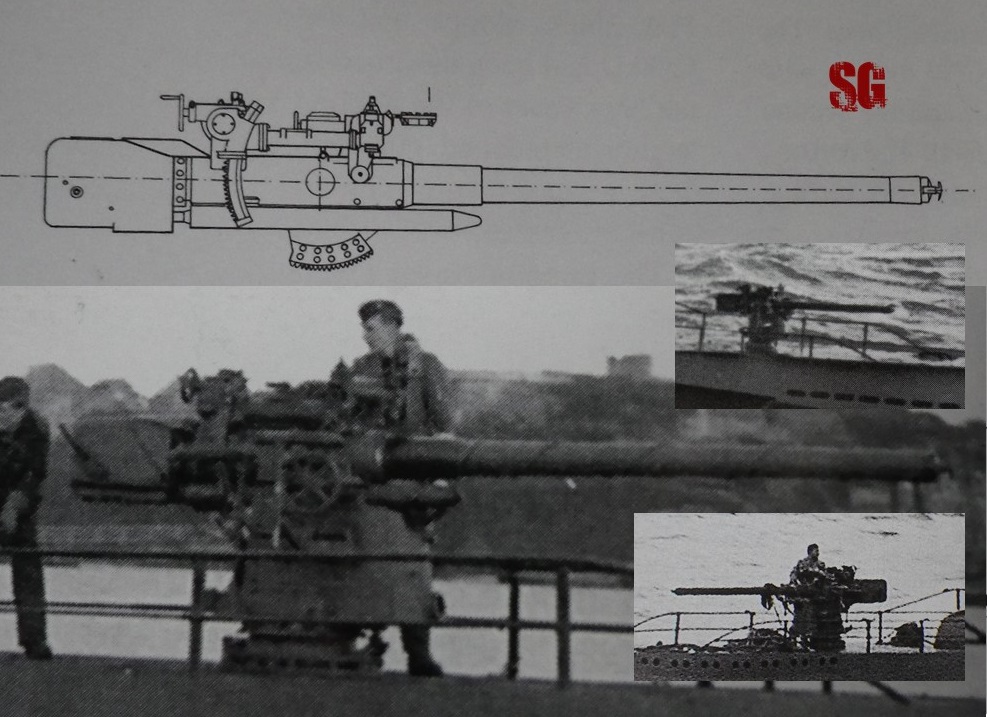
The main anti-ship gun for type VII U-boats until 1943. U48 sported one on her foredeck for most of her service (war patrols and later as a schoolboat until 1943).
The idea: the gun offered in the kit is rather inaccurate and its dimensions are more appropriate to represent the 10.5 cm gun of the type IX boats models (also produced by Mirage Hobby). I therefore decided to build U48 gun mostly from scratch (only keeping the original gun mount, appropriately reworked). My references for scratchbuilding the 8.8 cm gun are:
a) The following books:
German Naval Guns 1939-1945 by Miroslaw Skwiot (a). The book is magnificent and a real must if you want to have an in-depth look to german naval armaments of WW2. It features detailed information, beautiful artworks, technical drawings and hundreds of fine pictures. Mr Skwiot is a real autohority on the subject.
Super drawings in 3D: The VIIC Type U-Boot by Waldemar Goralski and Mieczyslaw Jastrzebski, Kagero Publishing (b). A fine manual with noteworthy information and stunning 3D artworks by Waldemar Goralski.
U-Boot VII Vol.1 by Marek Krzysztalowicz, AJ- Press (c). Great information, pictures and 3D artworks by Waldemar Goralski (“early” artworks when compared to the ones contained in Super drawings in 3D:The VIIC Type U-Boot but still beautiful artworks).
b) The 54 mm kit “Type VIIC U-boat deck gun” by Andrea Miniatures (Ref S5-S10). An excellent kit that I have in my stash from the early 2000s, actually a Christmas present from my brother which I haven’t been able to build yet and which, am afraid, will wait for a long time before being dealt with. Nowadays it helps me to understand the 3D shape of the gun and its details. And what an invaluable source of help! I have already measured and converted to 1/400 scale all the gun components and made an action plan : I will divide the build in 6 different sub-assemblies: gun mount, barrel, breech, recoil tray, superstructure, lateral arms.
GUN MOUNT
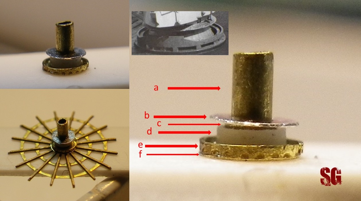
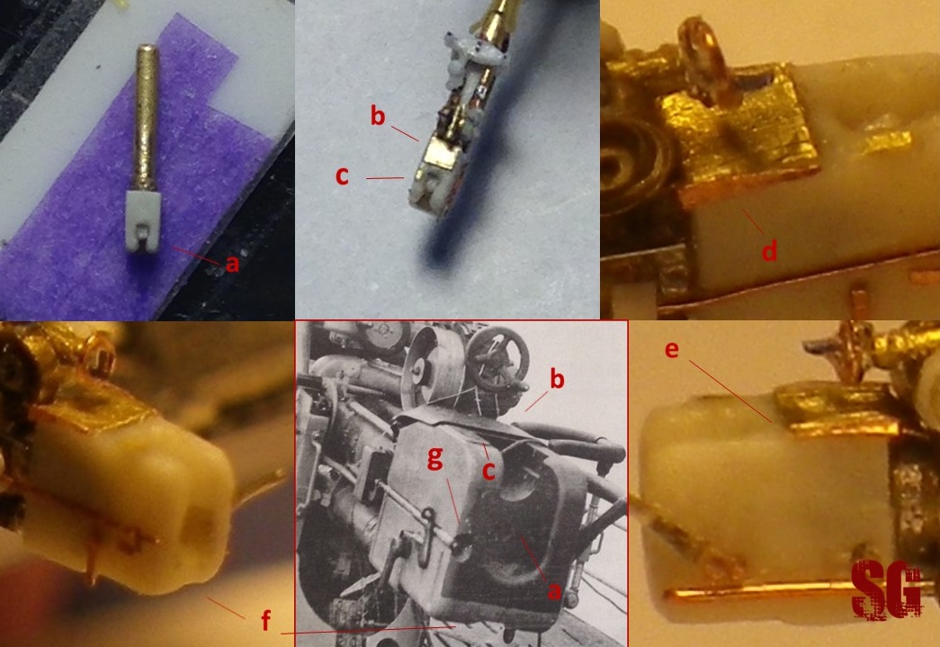
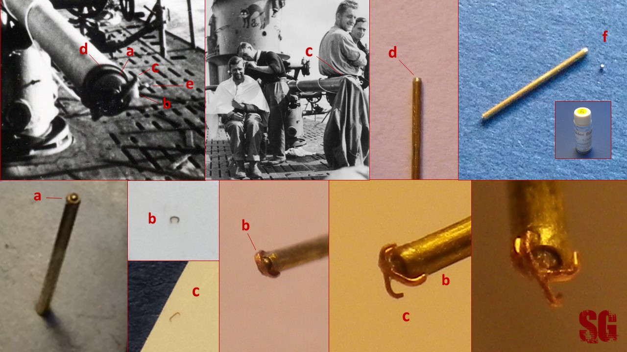
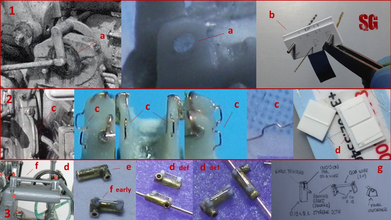
I started my work by separating the gun mount from barrel, breech and superstructure (a), then I sanded away all the details from the mount, carved it appropriately, filled a few holes/irregularities, reshaped the rear pedestal fairing with epoxy putty and added what I nicknamed the “lateral ears”, made from 0.2mm-thick/0.25 mm-wide styrene half disks (b,c). The “lateral ears” (aka the trunnions, as EJ Foeth – ontheslipway.com – kindly suggests me), were then shaped in situ with fine sandpaper. I finally drilled a few holes: the one on the frontside of the mount, for the tampion-housing (e), the one on the starboard side of the fairing (0.2 mm wide), (d) and the holes for the lateral arms, which must allow the lateral arms to be parallel to each other on both sides and to be perpendicular to the vertical axis of the mount (not an easy task) (f).
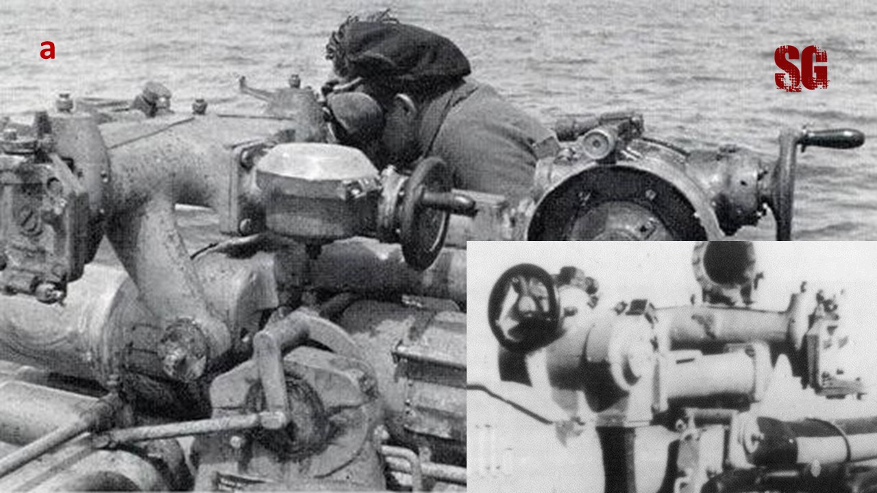
One word about the rear pedestal fairing shape: according to M Skwiot there were three different versions of the rear fairing and I found evidence that U48 sported the fairing version pictured below (“a” in the technical drawings)
thanks to details that I hunted down in two rare pictures of U48 (below, the magnified details):
At the end of an endless work which lasted many hours/modelling sessions I test-fitted the gun mount on the Uboat foredeck only to realize that it was over-dimensioned for the 400th scale (so very bad of me). Luckily, in Revell 1/350 VIIC kit (also part of my stash) there was a gun which is slightly under-dimensioned for the 1/350 scale and looks much more proportioned for 1/400 scale than the Mirage Hobby part. I started all over again with the same process I illustrated above for the Mirage Hobby gun mount. Below, the carving/shaping process has just begun on the original part by Revell (in the window):
and here’s the result of my work:
The new and the old mount compared:
The actual dimensions and the 1/400 mount compared to the 1/32 one by Andrea Miniatures:
There’s still a lot to do before I can say the gun mount is completed but I am happy things have started to move again!! (to be continued)
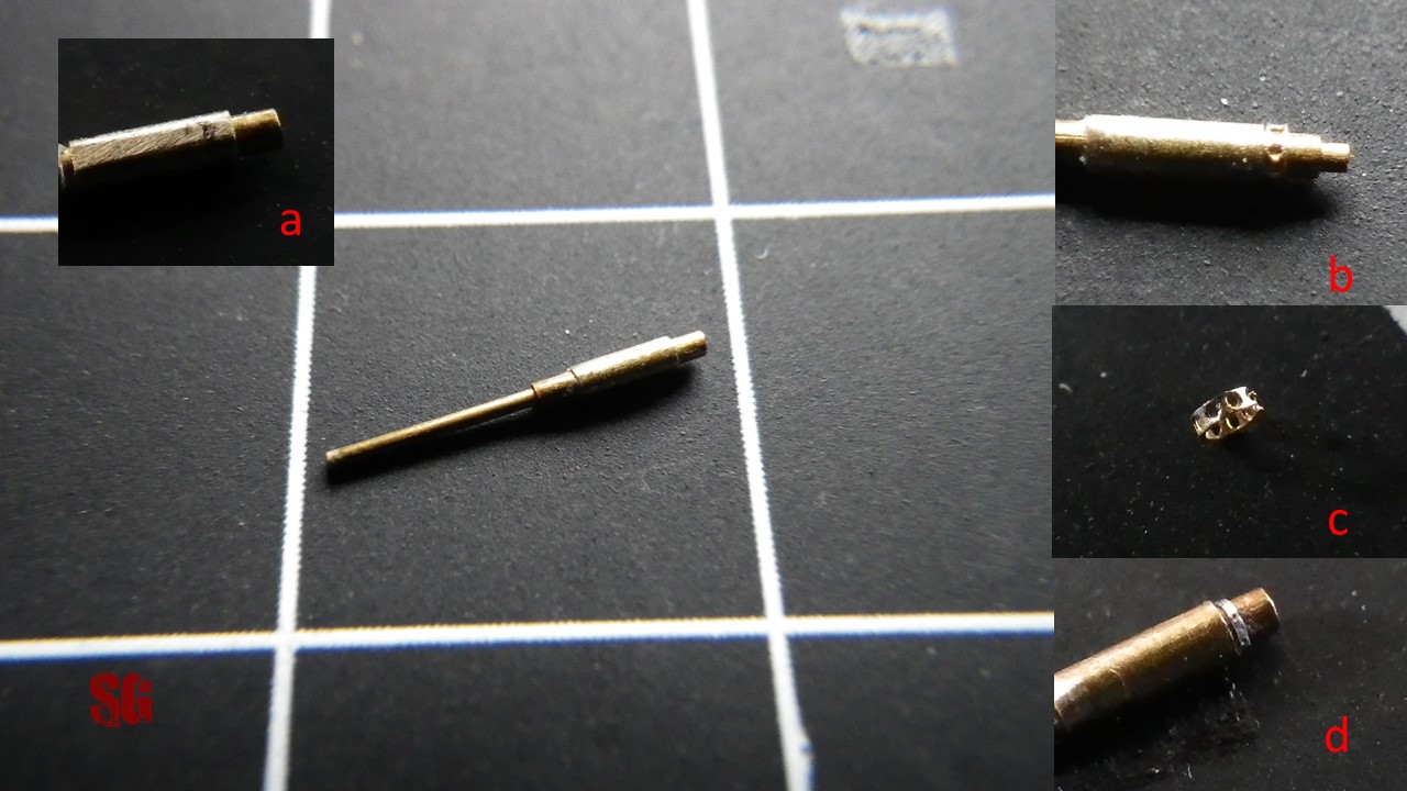
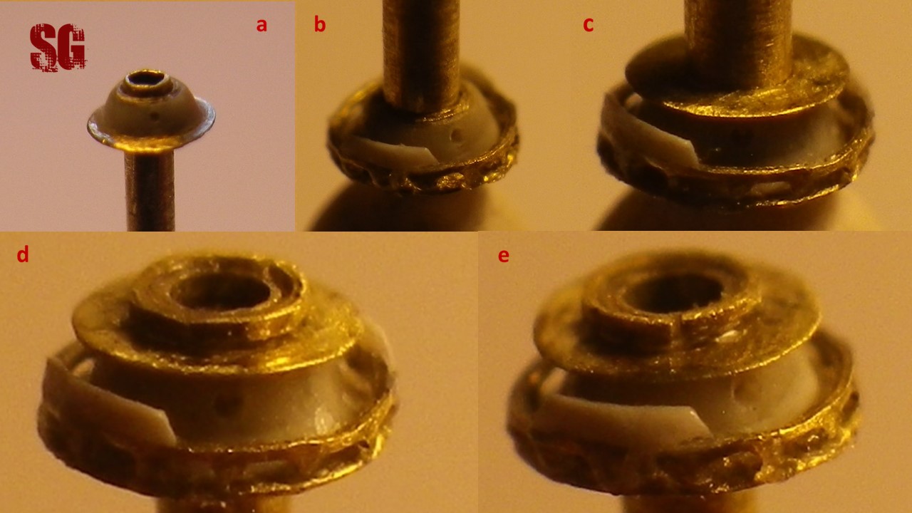
Pedestal (November 2015)
A composition of telescopic tubing of different calibers and materials (a=0.7 mm/brass, c=0.9 mm/brass, d=1.2 mm/plastic) and an aluminium disc (b) were positioned on the Mirage Hobby PE representing the round bolted baseplate (f). I added the toothed rim (e) which i have worked out from a PE catwalk from L’Arsenal, adequately trimmed and filed. Below: the real thing (window), the predestal alone (top left) and dry fitted to the deck’s anti-slip web PE from Mirage Hobby (bottom left). This is just a preliminary work and the parts are only dry-fitted. I think there’s still room for improvement and I am currently working on it, so stay tuned for a Part 2. (off the record: I am disappointed with the new WordPress policy of denying the uploading of clickable images that can be enlarged to their bigger original size)
Pedestal Part 2 (December 2015/January 2016)
After two months of hard work am finally happy to show you the improvement I had promised: the toothed ring (?should i call it the pedestal toothed fairing) was improved, the bolted baseplate was sanded flat and the pedestal was drilled twice. It took more time than I had originally thought (2 months!) because of the few modelling sessions i was conceded by work (an average of 4 per month) but most of all because the toothed ring was extremely difficult to make and when I had completed (an almost perfect) one, it pinged off to feed the monster carpet, causing a major blow to my morale (hehehe Yess!) and I had to start all over again. Let’s see the improvement in detail.
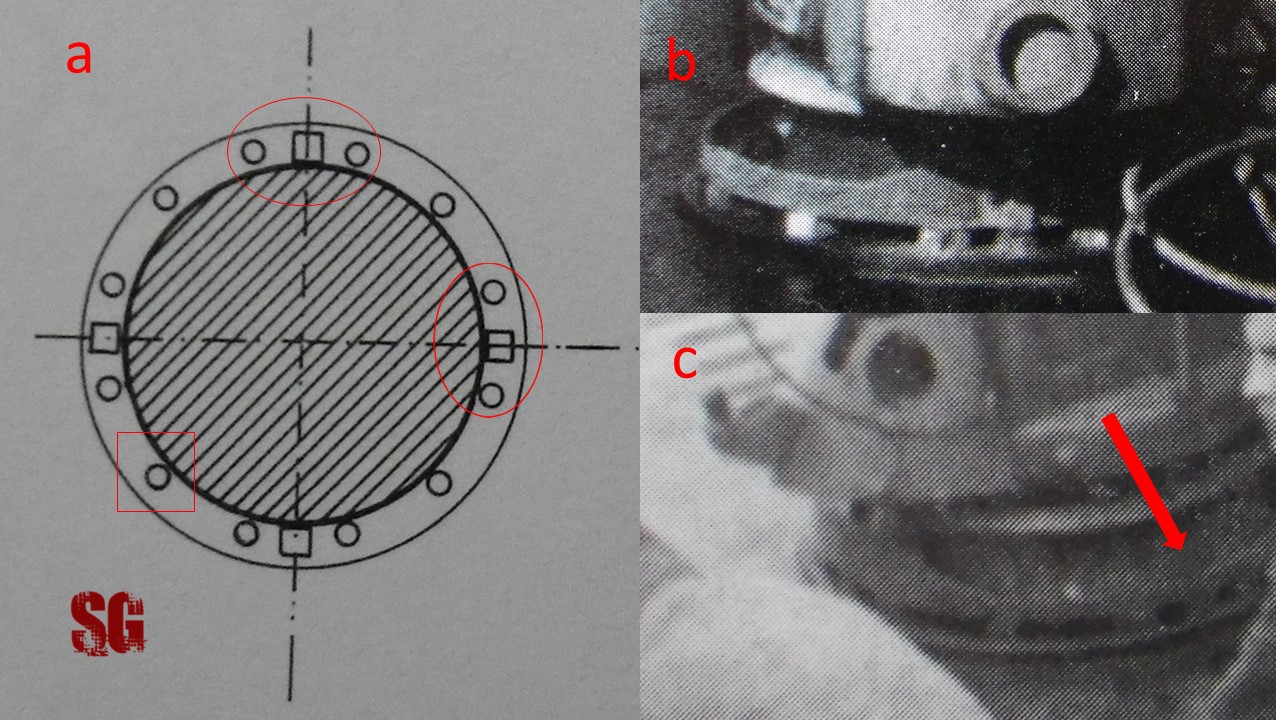
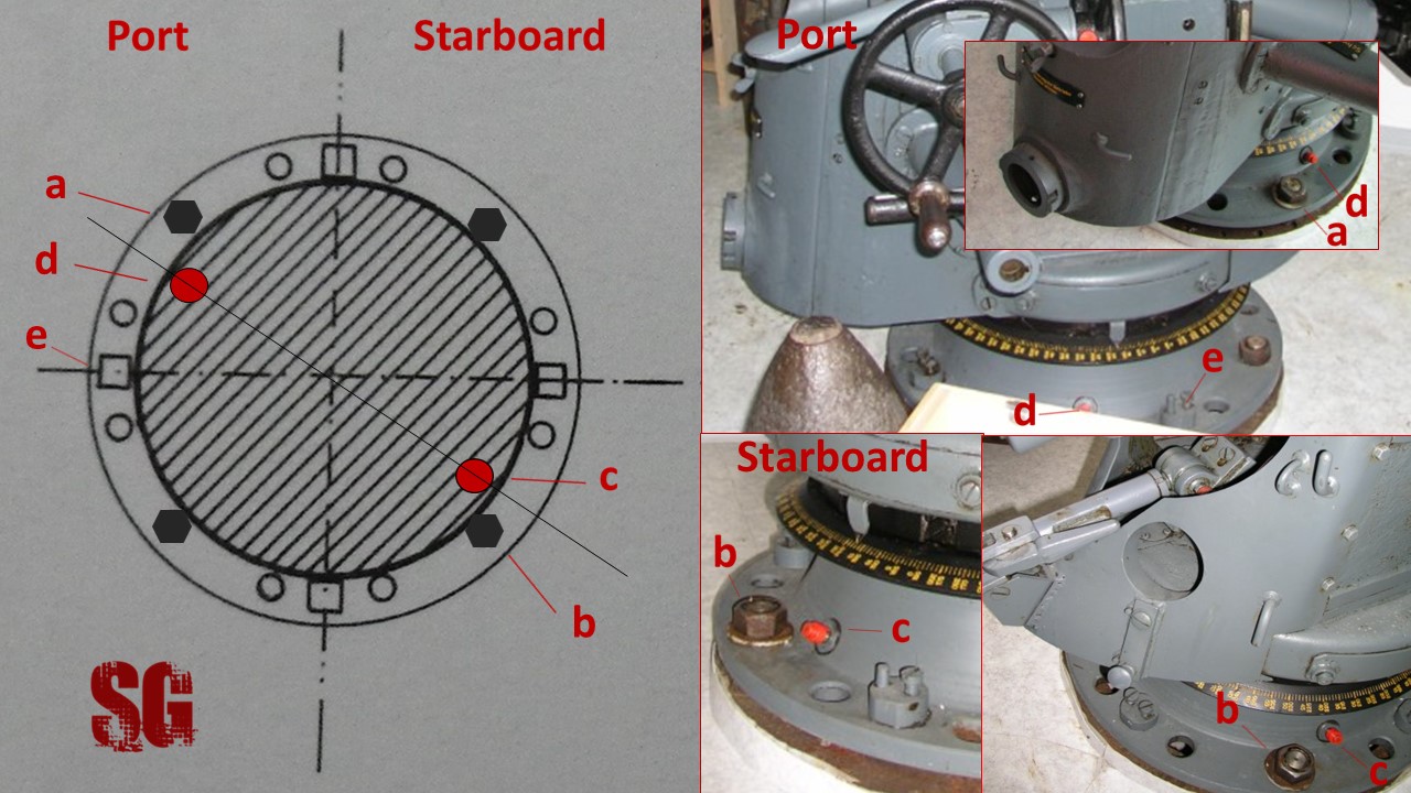
Toothed fairing. Curiosity: the real pattern of the “teeth” was somewhat peculiar. The “teeth” were arranged in groups of three at the cardinal points (picture below,a, ovals + b,c) and there was only one “tooth” per quadrant (a, square + b,c) for a total of 16 teeth distributed all along the circumference of the fairing. Miroslaw Skwiot gives the correct pattern in a technical drawing shown in his magnificent book. I verified the correctness of the pattern studying many original photos (it was particularly hard to find pictures showing the “triplets” at 3 and 9, but i eventually found a pair, c, arrow) and thought to share this information to provide a handy tip to those modellers who want to represent faithfully the gun in bigger scales (I am thinking of 1/72, 1/32 scale and the recent 1/48 U-boat releases), since the toothed fairing is a detail often ignored by many modellers. No, I am not that insane to reproduce the exact teeth pattern in the 400th scale (even if by mere chance I got very close to it! 🙂 )
The toothed fairing was made from a section of 0.08mm-thin brass net by Flyhawk, which was filed-to-size and shaped over a drill bit to obtain a ring of 1.5 mm. The height of the teeth is 0.06mm and so is the one of the frame, for a complexive height of 0.12 mm. I added two 0.08 mm-thick/0.13 mm-tall styrene crescents at 12 and 6. They were thermo-formed over a 1.5 mm drill bit and given a sloping lateral profile. The gluing phase was the most difficult part of the work and obtaining a stable joint without the bulking effect of the glue was particularly tricky. Unfortunately I had no luck with extra-thin CA and the pieces were eventually glued with diluted Gator’s Grip glue after several attempts.
Then, I sanded off the bolts from the outer ring of the round brass baseplate (above, right) to make sure to have an even surface for gluing the toothed fairing.
Finally I drilled two 0.15 mm holes on the 0.3 x 1.2 mm plastic tube representing the pedestal. The Jigster and the canal root files allowed me to obtain a smooth result.
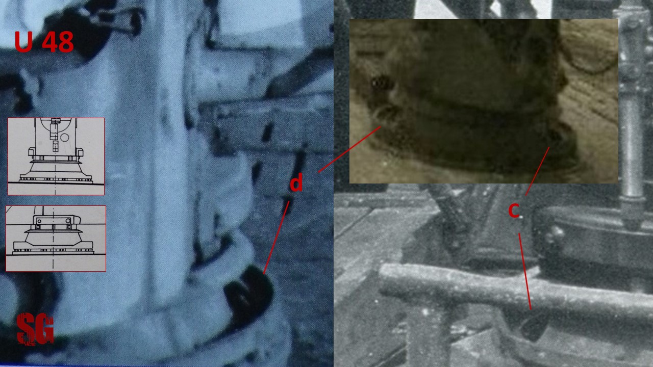
In fact there’s photographic evidence that there were two holes on U 48 pedestal at 4-5-ish and 7-8-ish. It’s been speculated that the holes were meant to allow lubrication of the pedestal mechanism, since they were provided with caps that had probably been removed or gone missing on U 48 (you can follow the research behind this finding in my U 48 thread on the AMP forum: http://models.rokket.biz/index.php?topic=858.0).
I test-fitted all the components of the pedestal to have an idea of the result, which I think is way better than the initial work.
LATERAL ARMS
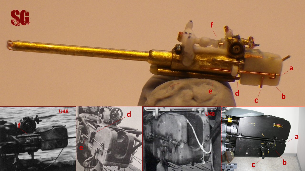
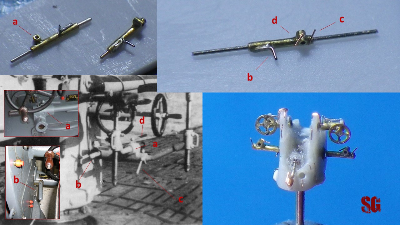
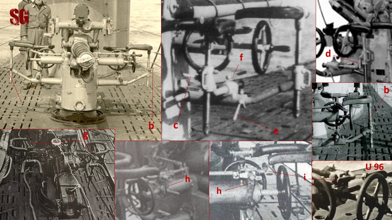
The 8.8cm gun had two couples of lateral arms:
two “Controls and Gearing arms” for the elevation and traversing control wheels (a); two arms (b) from which the braces for the elevator’s safety harness (c) and the traverse number’s safety harness (d) branched. Each of these braces had “Lambda” joints and “T” joints (circled). I started my work from the braces (c,d) and precisely from the Lambda joints. First of all i brought to 1/400 scale the dimensions of arms and braces. Without giving in to AMS (Advanced Modelling Syndrome which, am afraid to admit, has been affecting me for a looong time) a suitable caliber to represent the “controls and gearing arms” (a) in the 1/400 scale can be 0.3 mm and 0.25 mm for the lower arms (b). 0.3 mm (brass or other alloy) tubing are the smallest tubing you can get on the market. I chose Albion Alloys brass tubes, which have an inner diameter of 0.12 mm, they are an excellent product. Since 0.25 mm tubing are absent from the market I had to obtain them from 0.3 mm tubing by reducing their caliber. I used a cheap supermarket diamond file which I rolled over a tubing section placed on an old CD. The tubes must be fitted with a 0.1 mm rod, to avoid their deformation. Remember to wear a facemask and disposable gloves, and to wash file and CD with soap when you have finished. The tubing can be reduced to an even caliber by rolling the file over the entire tubing surface with a left-to-right motion. (the tubing in the pictures is bigger than 0.3 cal for demonstration purposes). I warn you, the procedure is long and tedious, so arm yourself with patience; the technique, on the contrary, is effective to get the desired result.
This way i obtained smaller caliber tubing sections for the lower arms and lambda joints (0.24 mm), which I cut to size and then soldered. In the picture below: 0.3 mm brass tubing (a); 0.1 mm rod (b) to represent the braces; 0.20-something mm brass rod obtained from 0.25 mm rod to fit Albion Alloys 0.4 mm-cal tubing (d); 0.24 mm-cal tubing obtained from the reduction of 0.3 mm tubing (c), then cut-to-size (window) and reduced to desired length by filing (the entire process of caliber reduction + cutting/filing-to-size is time consuming and rather boring).
One word about the “Lambda joints”: the angle between the branches of the joints is 60° in the technical drawings, 3-D artworks and original U48 pictures (a propos of pics, a Thousand Thanks Dougie Martindale!).
I am still a bit puzzled about the angle of the “Lambda-joints” for the traverse number safety harness brace: while the artworks show an angle of 60°, a close-up pic from U48 seems to show a steeper angle, but perspective might be deceptive in this case. In any case, consider an hypotetical steeper angle for that brace if you plan to make one and let me know what are your conclusions about that. I sticked to the artworks and soldered all the four “Lambda-joints” with an angle of 60°.
The soldering of the “Lambda joints” is one of the most difficult modelling tasks I was ever faced with. I used the “hot-blower and Koki solder paste technique” very well described and perfectioned by “Siara” Musialek and Glenn Cauley (check their outstanding modelling threads on the AMP forum: models.rokket.biz). I use a cheap butane blower, although I recently purchased the Dremel Versatip butane soldering iron, but i haven’t used that yet.
My faliure/success ratio in soldering very small parts with an angle of 60° with this technique is about 5 failures/1 success and that’s very frustrating because every time you fail you have to file-to-size the sections + align them properly time and again, and this alone requires time. The result of my work:
I know, the joints are not 100% perfect, but consider that the camera magnification is merciless, and bear in mind that the joints are barely visible to the naked eye, even at close distance (and even with an optivisor). I think what matters is giving an idea of what you are trying to represent. After all, aren’t we modellers some of the finest cheaters around? I think i will ignore my AMS for once, the risk of re-doing the entire process is to get bogged-down by the lambda joints indefinitely and not move forward. (to be continued)
Safety harnesses and vertical braces (May 2015)
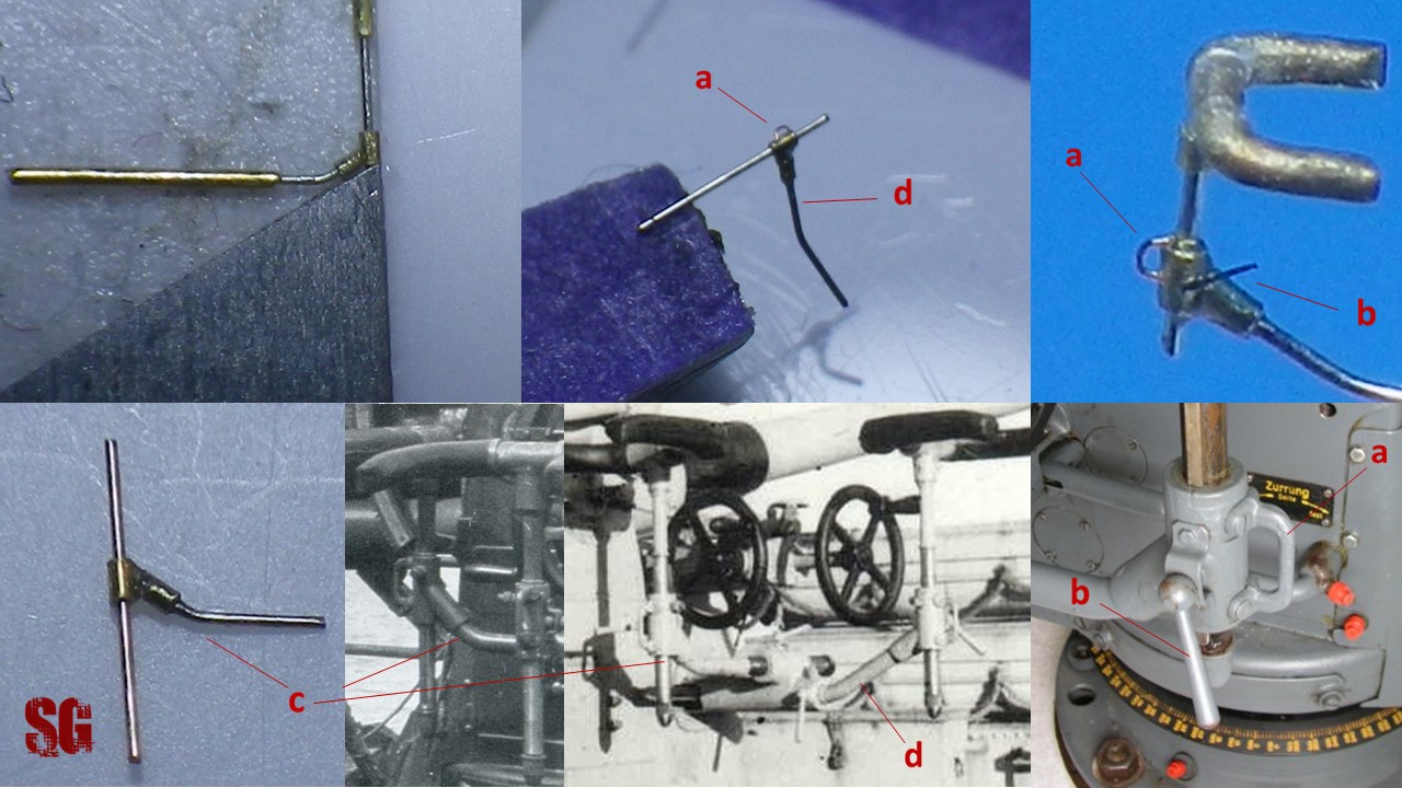
The vertical sections of the “T-joints” come from 0.25 mm-long sections of 0.21-0.22 mm-cal brass tubing. Obtaining a smaller caliber than 0.21-0.22 mm (from the original 0.3 mm) through reduction proved to be impossible: the tubes have their-own breaking point and when this is reached they just disintegrate under the file. The end-run sections are just o.15 mm long and preparing them was pretty painful. The picture below shows the sections dry-fitting 0.1 mm-cal rods. They will be assembled properly and glued to the harnesses once the rest of the gun is done, to make sure the correct proportions are respected.
The safety harnesses come from two lateral sections of 0.23 mm-cal brass rod, appropriately bent and shaped through filing, glued to a central section of 0.2 mm-cal rod. Yes, glued, i didn’t want to take my chances on soldering this time. Preparing the parts was very time consuming and a bad soldering would have meant starting all over again with the preparation phase (and an almost-sure nervous breakdown). I used very thin Rocket CA glue and reinforced the joints with diluted Gator’s Grip glue. The picture makes them appear more bulky than they really are.
(to be continued)
“Lower” lateral arms (12/03/2015)
I managed to solder 0.25 mm-cal tubing sections approximately 1 mm-long with 0.24 mm-cal sections 0.3 mm-long to obtain the arms (which, i must say, are almost invisible). This time I was lucky: only 1 failure and 2 successes with soldering! After soldering I polished the joints with fine sandpaper and test-fiitted the arms to the gun mount, just to get an idea of the result. Not bad at all! Wish I had some 0.2 mm cal tubing with an internal lumen of 0.1 mm though, the final outcome would have looked perfect.
Controls and Gearing arms (10/04/2015)
0.25 mm-Cal sections, 0.25 mm-long (these were tough to make!) were soldered to 0.3 mm-Cal tubing (slightly longer than the needed length of 0.7 mm, just to make the handling easier) with the usual technique. Two failed attempts, 2 successful soldering this time. Unfortunately I had to solder the brace for the traversing control wheel to the traversing arm and to the elevation arm to avoid dealing with a possible solder-related clogging of the traversing arm lumen. Nevermind, the control wheel brace will be trimmed to the correct length afterwards, and the elevation arms will be trimmed-to-size by filing after proper test-fitting to the gun mount. The distance between the outer margin of the traversing arm and the distal edge of the elevation arm (arrow, a) varies from a few tenths of a millimeter to nil depending on what reference source you follow (artworks by Goralsky, (a); artworks/technical drawings by Skwiot (b);Andrea Miniatures kit (c)) . Original pics don’t help much, since that area was rarely pictured from a close distance with the right angulation. I soldered the tubing sections with virtually no distance betweeen the edges but I am tempted to add a 0.13 mm-thick roundel at the end of the main arm, I’ll think it over.. In the meanwhile enjoy the result!
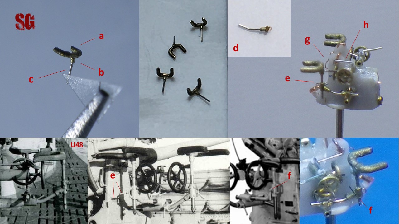
Flywheels (28/03/2015)
The elevation and traversing control wheels should have a diameter of approximatively 0.6 to 0.7 mm, depending on what reference source you follow. I had taken for granted that I could use some photoetched handwheels included in a set by Tauro Model but unfortunately size doesn’t always match with quality: the smallest flywheels in the set are thick and coarse (a). Since designing my own PEs with Autocad to have them produced elsewhere is something I am still unable to do (but I will in my next life, promised), I decided to make my own wheels from old-fashioned scratch after performing a feasibility study. Using copper wire and a cross-shaped section of fine brass railing to obtain a “full-metal” wheel doesn’t allow to reach a convincing result (b); reducing the size of the cross arms through filing is very time consuming; soldering is not an option either: I tried and it’s just not feasible with the soldering technique I commonly use. Gluing is the only other possibility left. I used Gator’s Grip glue successfully. In the end I decided to use a cross-shaped section of fine plastic net that I obtained from a ribbon, which I glued into a roundel made with 0.1 mm copper wire (c). Once I realized the feasibility of this technique I opted for 0.6mm diameter roundels made with 0.08mm-thick copper wire (d). The technique is straight forward: put the small cross (appropriately trimmed to fit into the roundel) into the roundel and apply a drop of very diluted Gator’s Grip glue with a fine pointed brush, “sucking” off the excess of glue with a thin strip of blotting paper. Gator’s Grip Glue is just amazing, fast drying and with a good bonding quality. Non toxic, thins with water, dries to a completely transparent finish.
I am pleased with the result. I managed to make eleven wheels in an afternoon (the same amount of time I spent for making just one “full-metal” wheel). I will choose the best 4 of them for the Controls and Gearing Arms. Notice the residuals of glue in some wheels, they are completely transparent and invisible to the naked eye, however i’ll try to clean them up. The wheels still miss their knobs, that will be added in due course. Below, the actual dimensions.
(to be continued)
Recoil tray
I made the recuperators from 2 x 0.3 mm-cal brass tubing sections which were separated by an interposed brass railing section. The three pieces were soldered together with the usual technique to obtain the tray. The tubing sections were then fitted with 0.1 mm wire and the tips of the recuperators were shaped with Tamiya epoxy putty (arrow). I painted the recoil tray with diluted Gators’ Grip just to make sure the putty tips are secured properly to the rest of the tray. This caused some debris to form (invisible to the naked eye but clearly visible on the magnified image at the left end of the cylinders),which has already been taken care of.
Recoil tray take two (Oct 2015)
After a forced stop due to an unusually hot summer and too much hospital work I am finally back. Re-did the recoil tray since test-fitting to the gun mount the one I had already completed proved to be unsuccessful due to a few tenths of mm too many (the soldering was too bulky and made the tray too wide). This time I spaced the recuperators with a 0.13 mm styrene spacer, gluing the ensamble with Gator’s Grip glue. Here’s the result:
BREECH
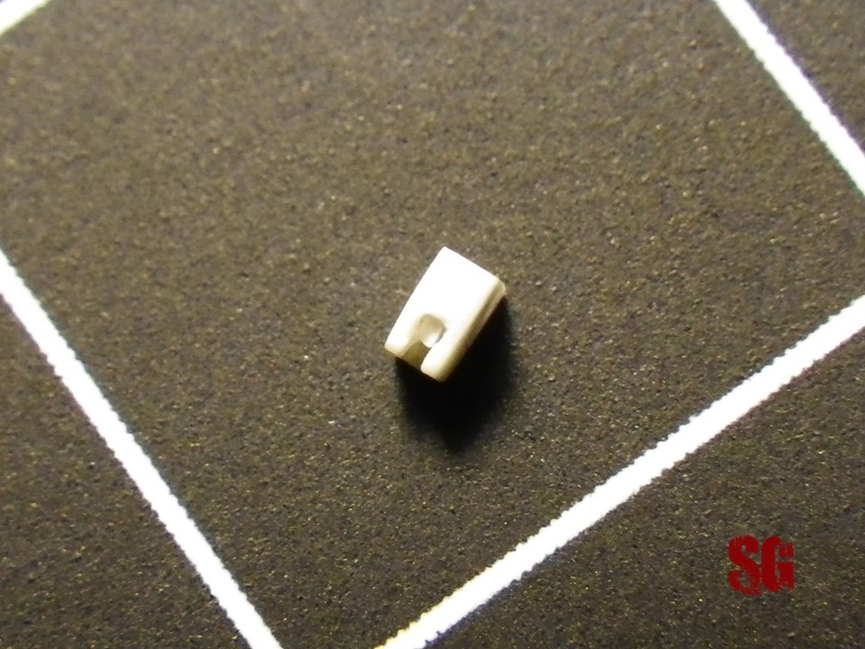
Part 1 (November 2015)
A piece of styrene measuring 1 x 1.3 x 1.5 mm was cut, shaped, drilled and carved to represent the main frame of the breech. The most difficult part was shaping the U-shaped breech ring and the housing for the breech-block. I corrected minor errors with epoxy putty which was preferred to toluene-based fillers because of the potential risk to melt or deform the flimsy walls of the breech housing from the use of the latters. The breech still needs to be completed with the breech block (am studying the feasibility of making one), various levers and rods and the fore top fairing, which i hope I’ll be able to complete soon. The preliminary results:
Part 2 (February to April 2016)
I’ve been through difficult times lately and now I am slowly recovering. The last few months saw just a handful of modelling sessions during which i was able to sculpt a breech block from a very thin strip of styrene (0.3 x 0.3 x 0.5 mm) to fit the breech block housing. I have also drilled very small holes onto the breech sides to host the various levers/rods that were there in reality. Drilling holes in the right places on such a small surface proved to be quite a task and more than once I had to fill the misplaced holes with epoxy putty, wait for the putty to cure, sand the repair flat and then re-drill the holes until I was satisfied (a pretty silly work). It took time (no pictures available at the moment, I’ll shoot some as soon as I am able to complete the breech top fairing). Am afraid to tell you that I am facing another forced stop of my project due to “real life interfering with progress” once again. No worries I won’t give up, I’ll be back at it sooner or later. In the meanwhile enjoy my meager progress:
Part 3 (April 2017)
Hi, it’s been a while. I’ve been unwell lately and am just recovering from an operation. The pros: i have some more spare time to reconcile with modelling. When i was unwell and in an hospital bed i thought i really had to start working again on my project and and try not to leave it unfinished. So: the shipyard is open again (?should i say the gun factory 🙂 ) and some little steps forward have been made. I added some provisional details to the breech (port side: 0.05mm copper rod trimmed and shaped, starboard side: 0.08mm rod), which have been dry-fitted for scenic purposes. The portside lever is not the definitive one, a better-looking lever will be shaped. The other flat detail aft of the lever will be crafted and added too. The horrific hole has already been taken care of and the starboard side dent will be fixed with epoxy putty soon. Well, i hope to be back on track, but i wouldn’t bet all my money on that. I’ll try my best to keep this project alive, health and spare time permitting. Glad to be back anyway! Enjoy the results:
Breech fairing (April 2017)
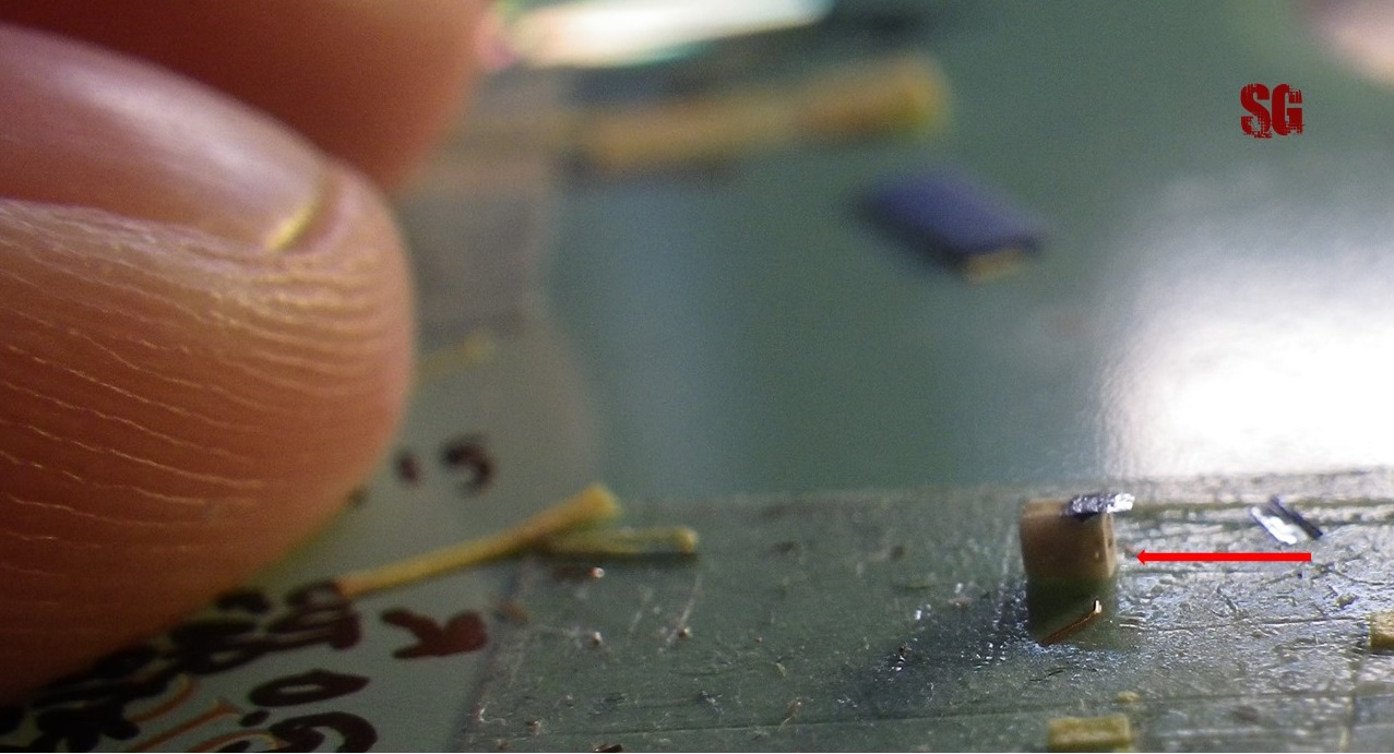
The breech fairing had several subvariants: “squared” (a), “multi-faceted” (b), “flattish” (c) etc, as i had the chance to observe in the hundreds of pictures i have studied. There are different possibilities to build one from scratch but in the 400th-scale priority must be given to materials causing less bulking effect, thus narrowing down to three different materials: styrene sheets (minimum thickness 0.13 mm), CA-soaked paper (about 0.1 mm thick, it can be sanded to some extent) and aluminium foil (0.01mm-thick). I opted for aluminium and managed to cut a trapezoid to represent the fairing. I found that working with aluminium in such a small dimension and thickness is pretty difficult because alu gets crumpled or perforated very easily by tweezers and blade. So, not many chances to craft the subvariants of the fairing but rather trying to make do with what you get. Making and bending the lateral “wings” was particularly tricky.
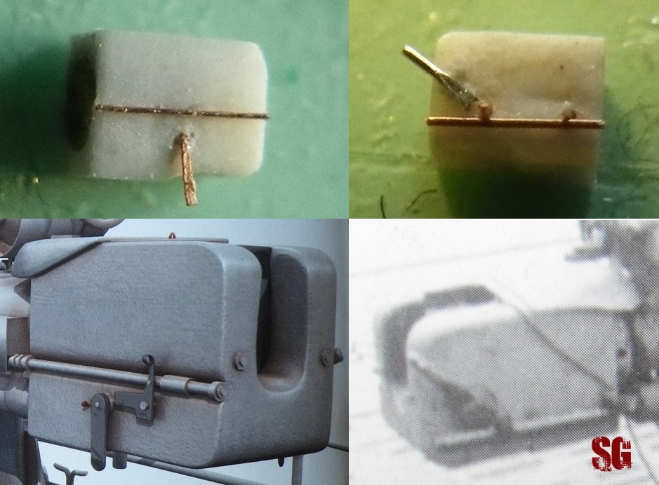
Here you can see the actual dimensions of the fairing dry-fitting the breech. The fairing will be given a sloping angulation of the forward free-end once the breech is connected to the barrel. The arrow points out the fore hole on the starboard side of the breech which was moved forward to get a look closer to the real thing.
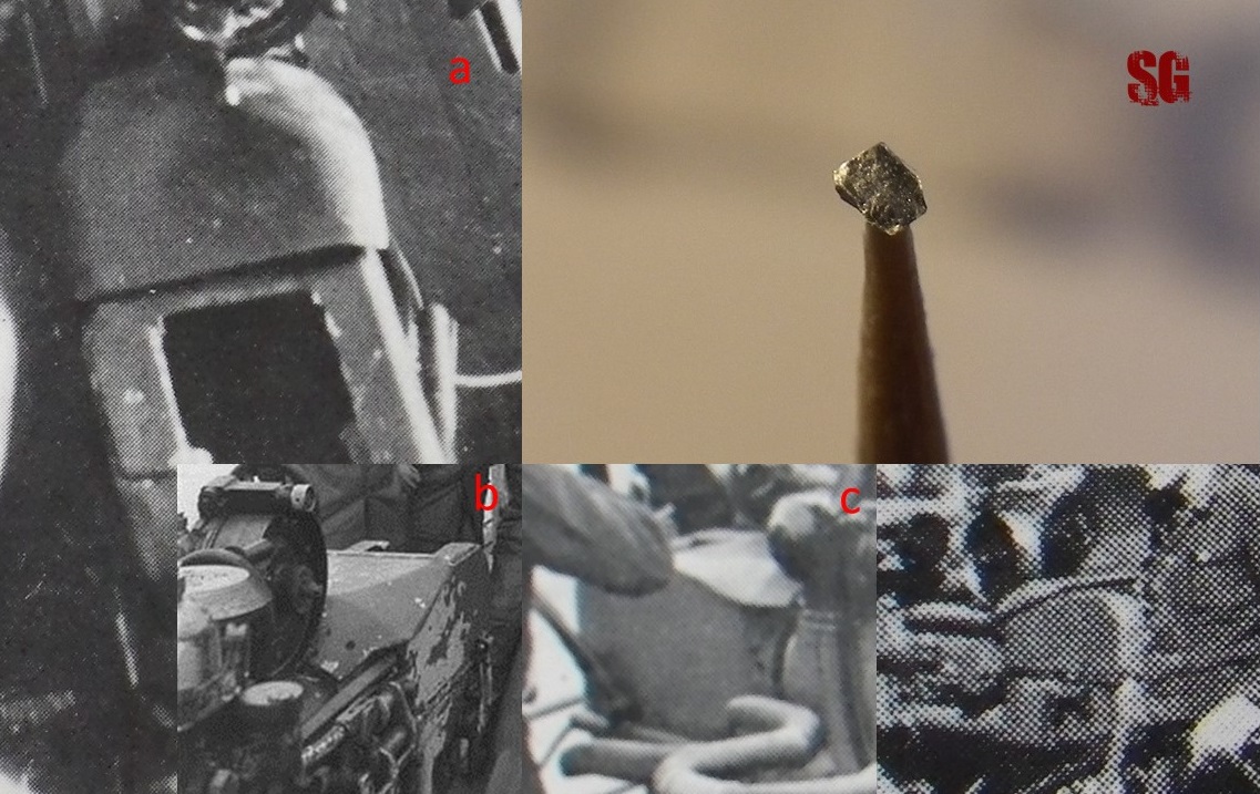
BARREL (April 2017)
The 8.8 cm tube had a slight variation of the outer profile with a decrease in size at the middle-last section of the barrel and a sloping slight increase in diameter at the muzzle. The scale effect must be considered here, because as you may see in the pictures below, the outline of the barrel looks like it’s even and perfectly cylindrical when seen from a distance, something to be kept in mind when dealing with small scales such as the 400th.
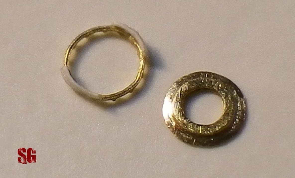
I used three telescopic sections of Albion Alloys brass tubing with an outer diameter of 0.4, 0.6 and 0.8 mm, measuring different lenghts that were taken according to the technical drawings by Miroslaw Skwiot. The bottom surface of the bigger section was sanded flat to host the recoil tray (a), and the middle section was left slightly longer than the actual dimensions to connect to the breech and host a perforated ring which was present just fore of the breech. I crafted 2 different rings: a brass ring some 0.25 mm-tall obtained from the fret “1/700 perforated beams” from L’Arsenal (b,c) and a thinner 0.18-ish mm-tall ring obtained from 0.01mm-thin aluminium foil (d) which i perforated with a 0.06 dental root file. The alu ring is really flimsy and difficult to manipulate as it is nearly invisible. I still have to choose between the two. I like the clearly-visible holes on the brass ring but the bigger dimensions of it when compared to the alu ring just got me thinking. Maybe less is more in this case.
(to be continued)
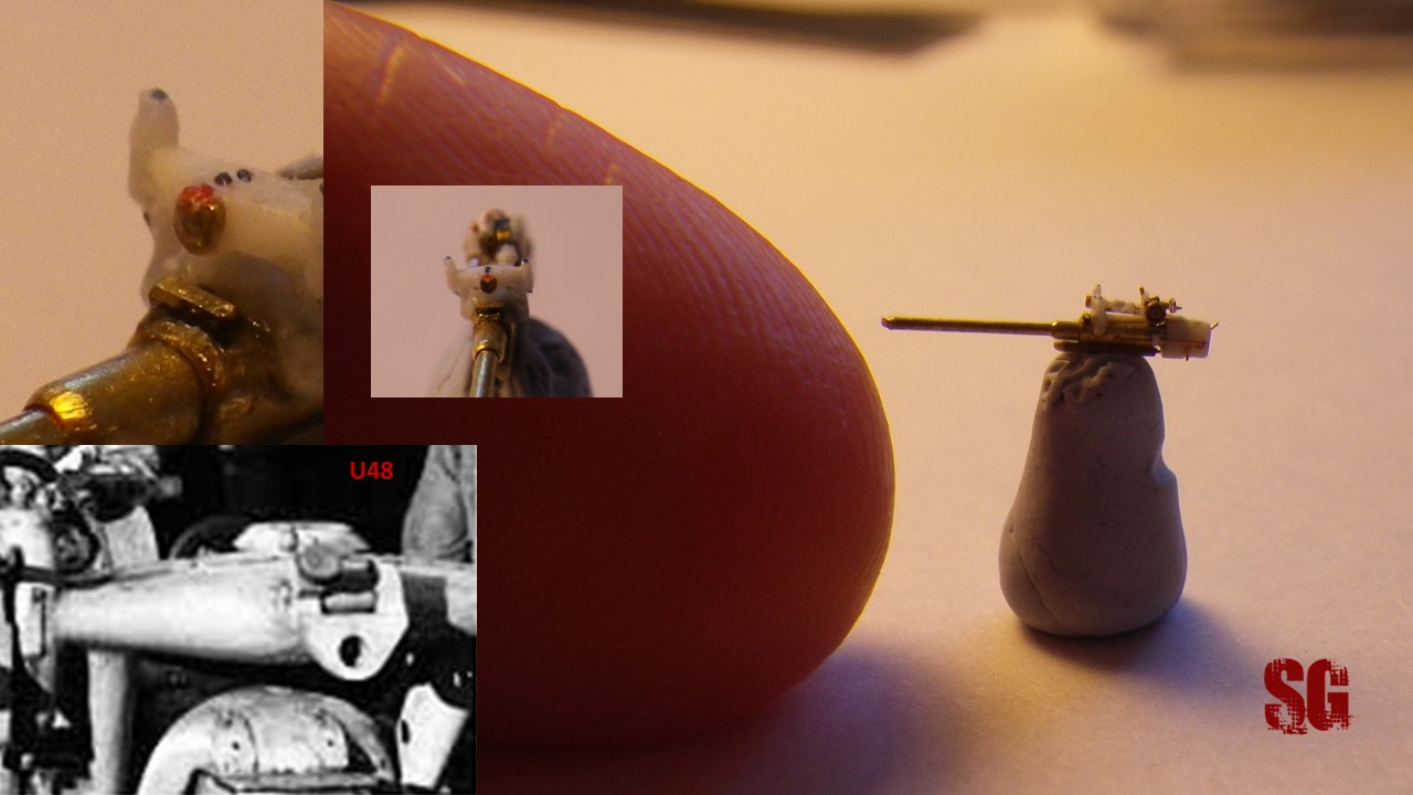
GUN SIGHT (superstructure) (May 2019)
Hi, It’s been a while! 2 years.. Illness, post-op recovery, (too much) hospital work, major works at my flat: time-consuming! Now it seems i’m finally back to modelling, but my hands and skills got rusty, too bad stopping for such a long time. I’ve started again with the bigger parts of the gun sight. They seem way too small for my eyes and hands. Anyway, the sight components were crafted from 0.5 mm squared styrene strips, downsized through sanding using a very basic jig (to 0.25 x 1,9 mm-trapezoid- and 0,25 x 0,13 mm-ovals-) and shaped with very fine sandpaper and scalpel blade. Now the question is: will I be able to align and glue the pieces together? Let’s see what life concedes me in terms of spare time and monthly modelling sessions. Meagre progress but yes, things are finally moving again!
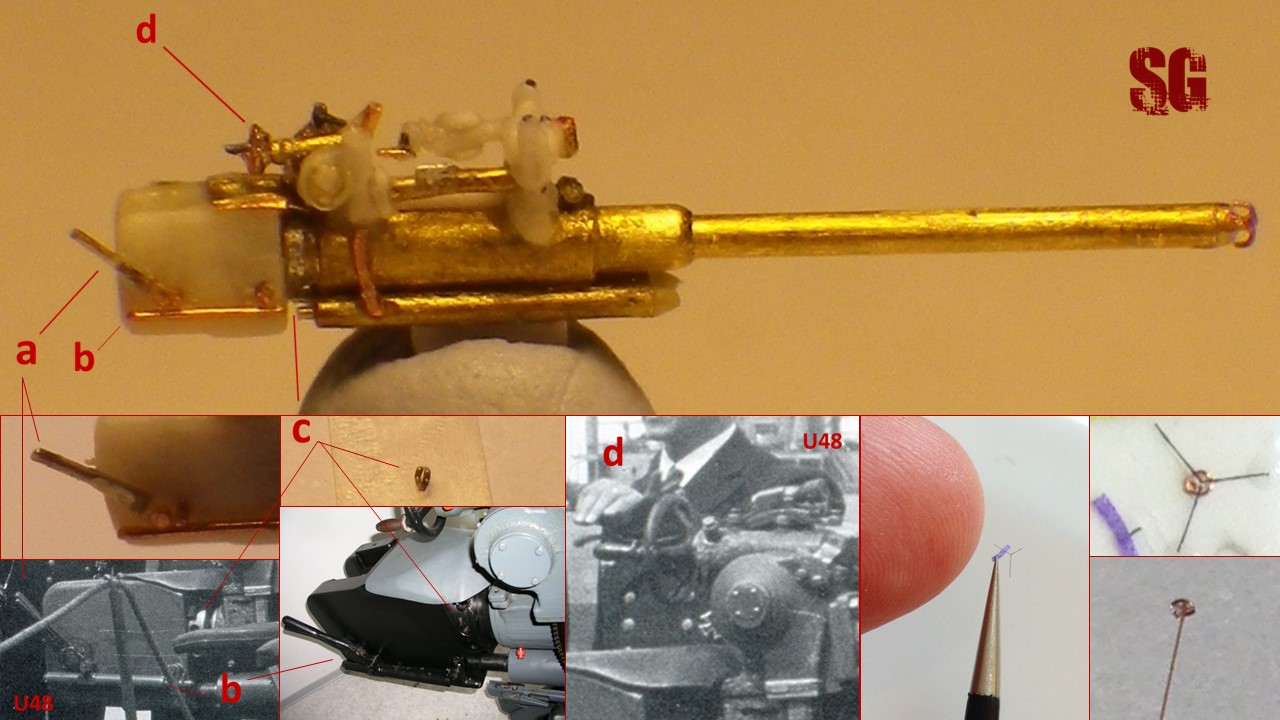
Main sight (March-April 2021)
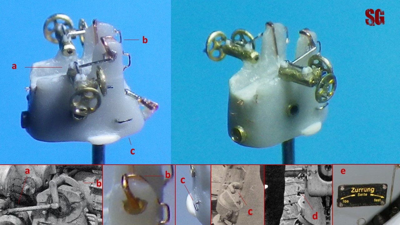
It took me more than a year to get sufficient spare time and stamina to dedicate myself again to something quite unattractive for me. The main sight proved to be a very tough nut to crack, because of its complexity and most of all because of its small dimensions. The main “H-shaped” structure, what I figured out to be a rangefinder, is linked to an arm (b) hosting the deflection setting dial (a), which ends with a flywheel (c). After gluing the pieces forming the main body of the rangefinfer (see previous section) I crafted the dial’s arm (0.2 mm diameter rod from stretched sprue, 0.4 mm-long), the dial itself and the wheel (0.3mm roundel, 0.05-thick) with its handle (0.05 mm copper wire, 0.25 mm-long). Gluing all the pieces together was really difficult. I used Tamiya liquid cement for the main body, dial’s arm and to build the dial too; odourless Roket CA was used to build the flywheel and for putting all the tiny bits together. The sequence of events due to several and unforseen ungluing of the pieces has been: one step forward, two steps back, one step forward again, standstill. That was painful.
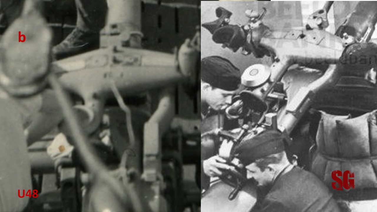
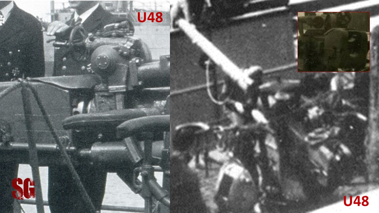
Curiosity: there were two main different versions of guns (and sights): one version, apparently a later feature, in which the dial arm is linked to the main body by means of a bolted plate, a) (the arm linking to the starboard pillar of the rangefinder is also bolted, bottom right, but that’s another story hehehe)
and an early version, (below,b) that sported no bolted plates to connect the main arms to the main sight. The starboard arm bridging from the deflection setting block to the main sight was connected to the deflection block by means of a bolted plate only, at its proximal end. U48 was equipped with this gun version -at least in the patrols 6 to 10 under Rosing and Bleichrodt- the historical period I have chosen to depict my model.
The completed main sight: notice that i have added the main “pins” on top (and bottom) of the lateral pillars and main body of the rangefinder, some microscopic 0.0-something bits taken from a very fine plastic ribbon mesh, glued w CA (that drove me insane!). The fore surface of the rangefinder sports the retractable mount for the lead sight, which is a modified perforated-section of a ShelfOddity PE (yes, I have already taken care of that glue residual in the hole of the brass lead sight mount). The result of my work:
I apologise for the lousy quality of the pictures but the overall build is very small, my camera strains to shoot defined shots and the white-on-white styrene is not photogenic at all. The actual dimensions, note the crisp look of the sight seen from a distance:
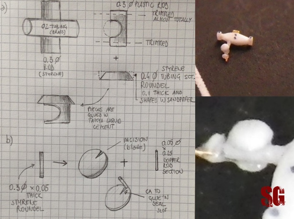
The main sight is made of 15 very small components that was impossible to photograph singularly due to their dimensions; below, the technique i used to build the dial and the flywheel, on a planning sketch:
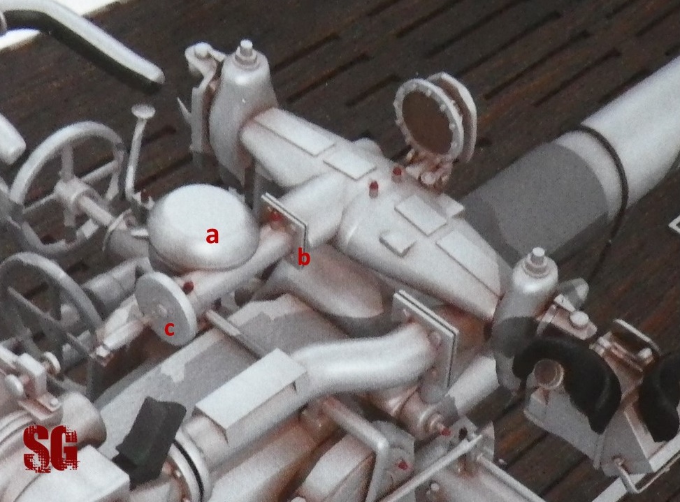
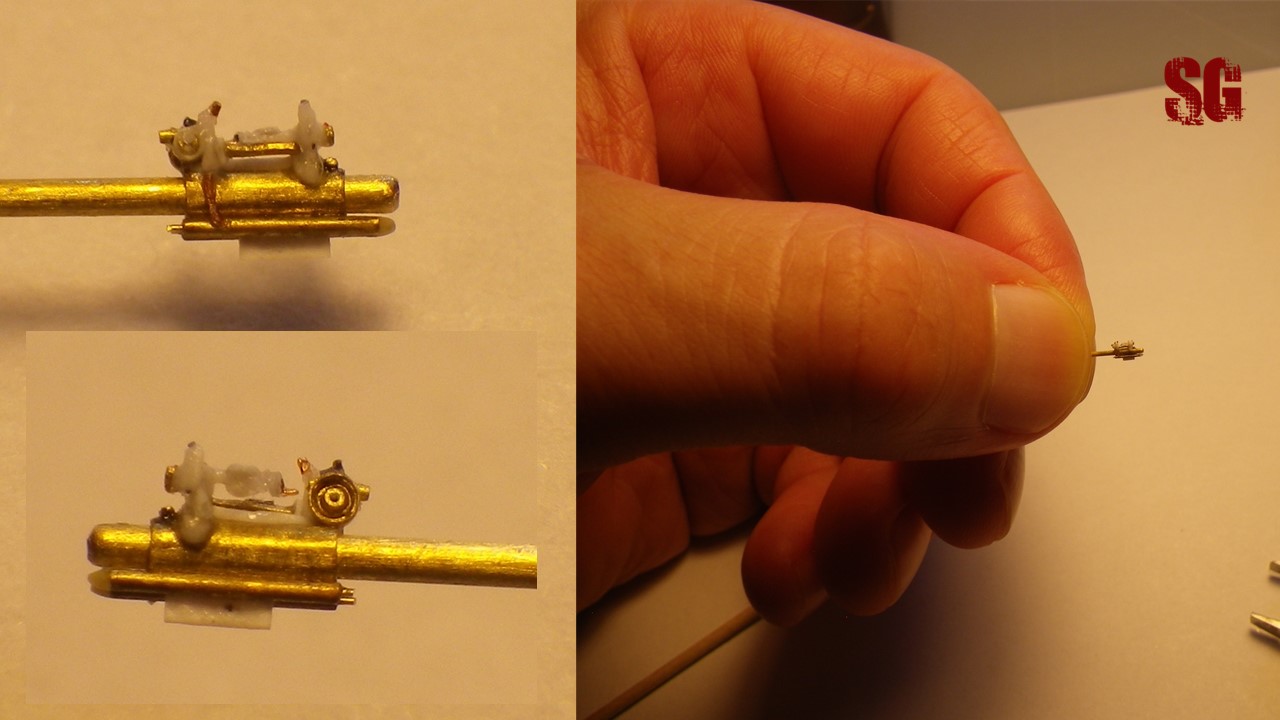
Sight base(May 2021)
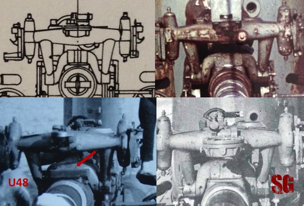
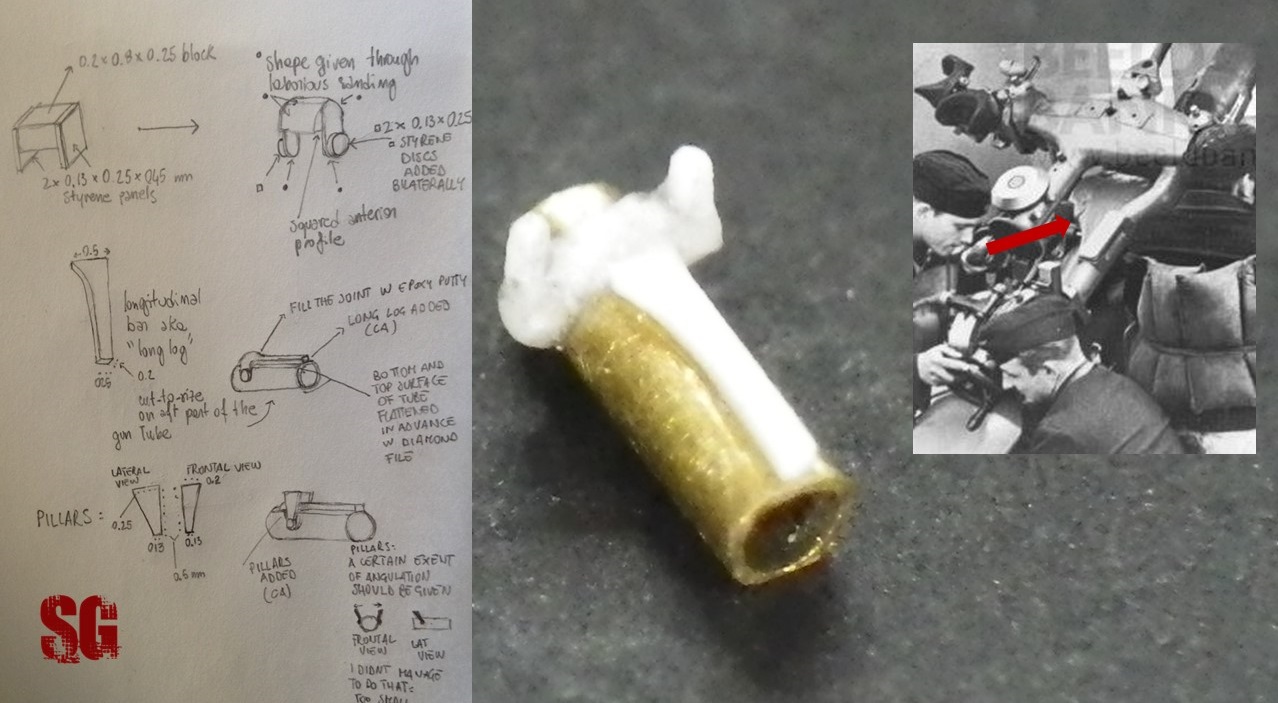
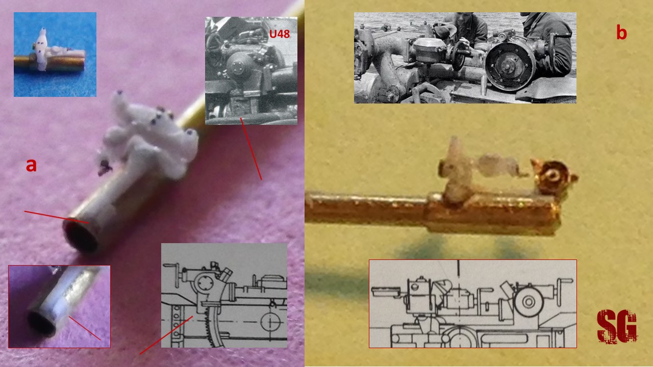
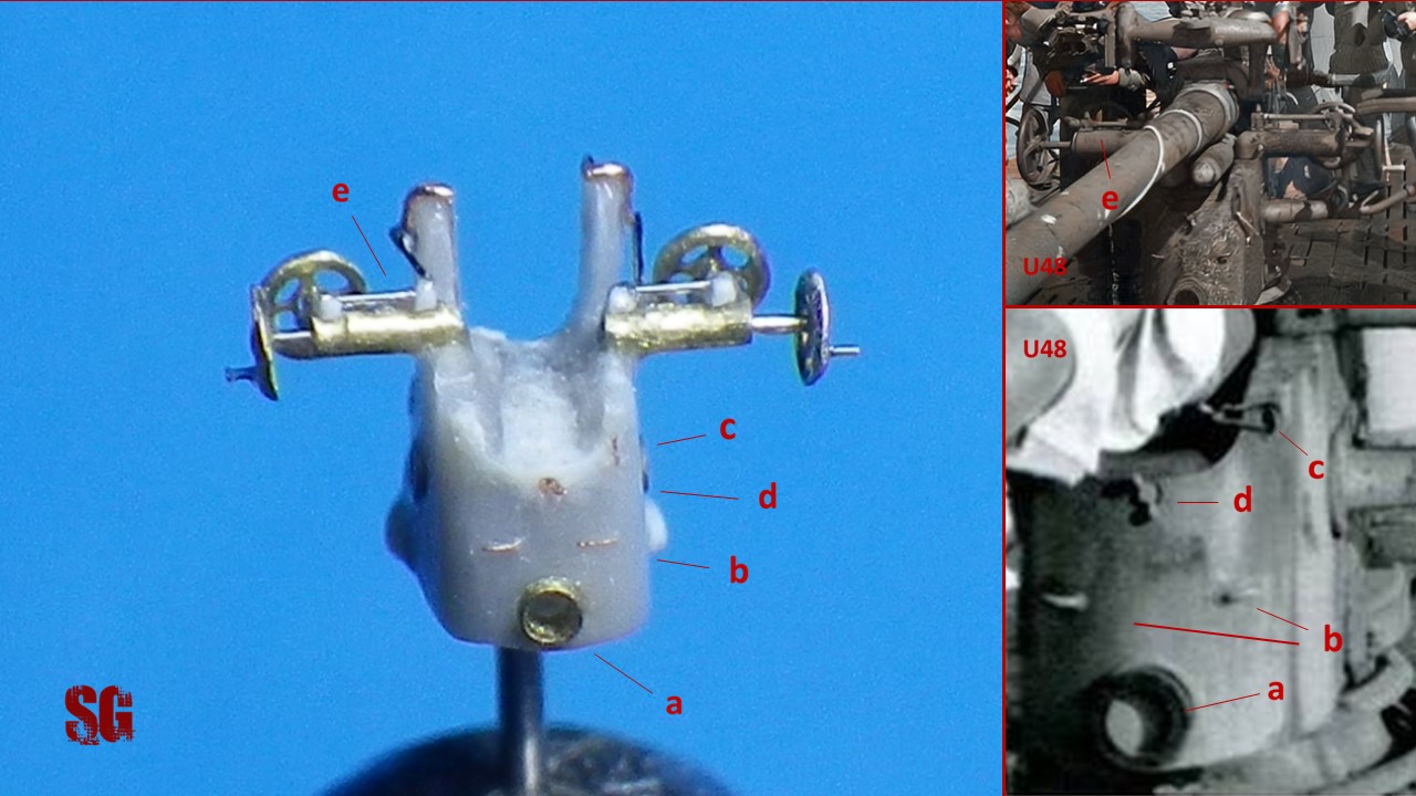
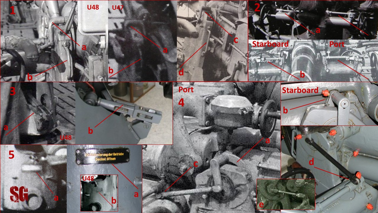
Sight base/mount is a complex structure made of several elements: a) the base, with its round shape and squared front, b) the bilateral pillars holding the main sight, c) a longitudinal element (i nicknamed it “the bar” or the “long log”) linking the sight mount to the aft part of the gun tube where the deflection setting block is located. The bar has a crescent shape at the mount-end and continues into the mount as a unique block. A closeup pic of U48’s 8.8 gun revealed an additional transverse element located immediately before the sight mount (below, bottom left, arrow): i ignore what it might have been (? a rubber cover of some sort maybe) but i am going to recreate it anyways at a later stage.
The sight mount is a composition of several small styrene parts that were sub-assemblied, glued to the aft section of the gun tube and subsequently shaped through sanding. The main difficulties encountered were: a) crafting the single pieces, because of their small dimensions and b) gluing the pillars: several attempts with Roket odourless CA glue failed, the pillars refused to glue or detached in more than one occasion, the bond wasnt strong enough considering the minimal quantity of glue applied. The problem was solved using old-fashioned Loctite Superglue that eventually did the job. In the reality the sight pillars leaned forward and laterally (see technical drawing in the above pic and picture a, previous post) but giving them an inclination exposed to mis-alignement of the pillars and thus i only gave them a minimal degree of inclination. You can see the result of my work below:
Below, the explicatory sketch of the build, with the dimensions of the various elements and detail of the “log log” prior to epoxy putty application and smoothing of the top edges (sorry for the overexposed/blurred pic, yess! I need a better camera) :
To be continued
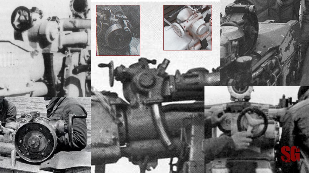
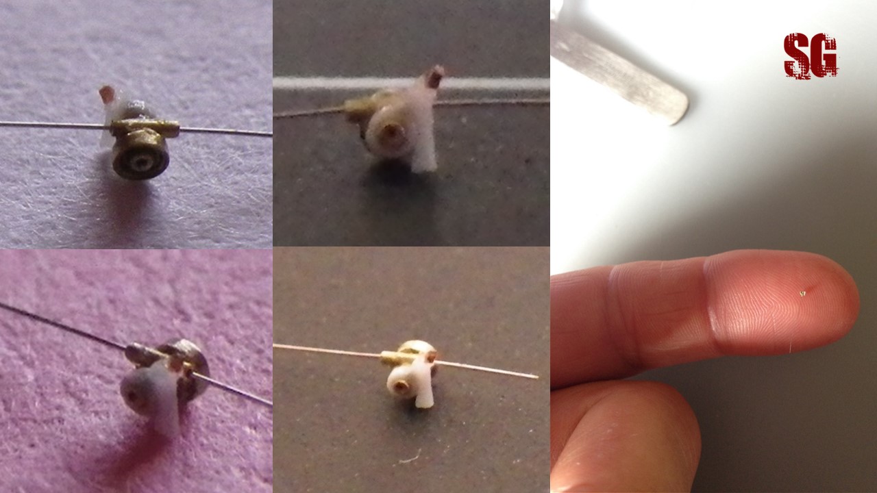
Deflection setting block(June-July 2021)
The deflection setting block lies on the after part of the gun tube and has a very complex shape, as you can see for yourself (for extreme magnification of the pic doubleclick on the thumb):
Curiosity: Two main variants of the deflection block can be identified. U48 sported the variant with a tapered/semi-conical starboard end and a different shape of the fairing for the toothed crescent (below, left). This feature must be considered when representing the 8.8, especially in the bigger scales. Off the record: also U47, U46 and U96 sported the same version of the deflection block as U48. In fact they sported the same gun variant, as shown by photographic evidence.
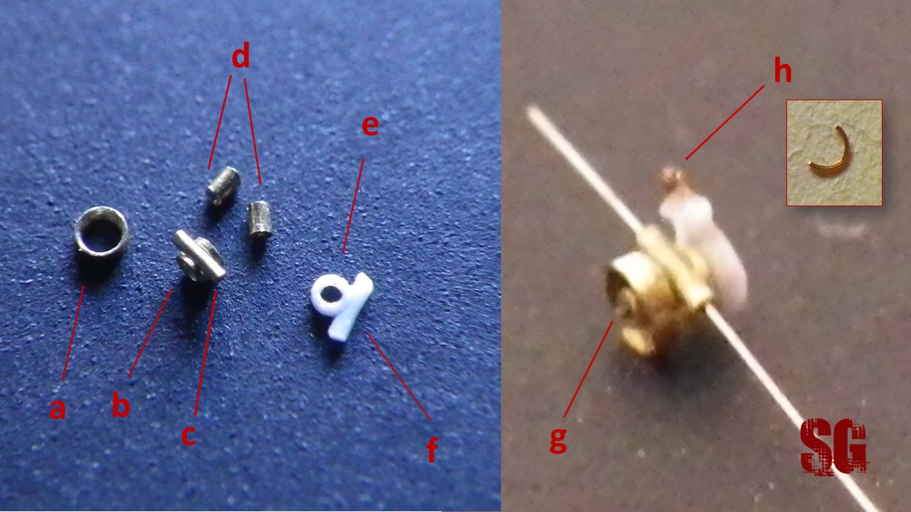
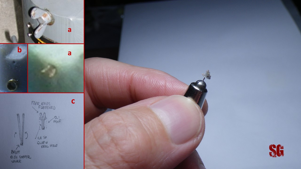
A composition of brass microtubes was assembled w CA. Port to starboard: 0.7 mm-wide x 0.2 mm-long roundel (a), with thinned walls only on its port side (that was challenging!) + inner 0.3×0.3mm section (d) in a 0.5×0.5mm section (b) in which i carved a slot to host the 0.2×0.8mm section to represent the handwheel arm (c) + 0.3×0.5 mm section (d starboard, higher in the pic) + the starboard fairing, made of a handcrafted styrene roundel (e) 0.5-wide, 0.3-cal x 0.2 mm-long, glued to a 0.2 styrene vertical section (f) that was thermoformed and indented on its convex side. Ah, icing on the cake: the “pin” in the middle of the “big wheel” is a 0.06mm-diam nickel wire section, protruding from the 0.3 section just the right few tenths of mm (g). Finally, the top part of the toothed-crescent (h), a section taken from a 1.2 mm-wide roundel of 0.1 mm-thick copper wire flattened with the help of flat-nosed pliers to reach the thickness of 0.08 mm and a square shape (window, top right).
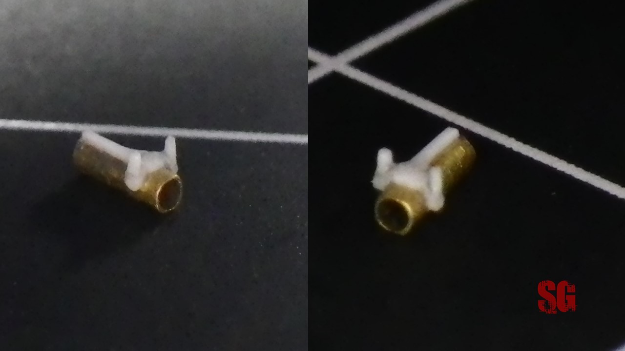
Assembling the block was tricky: to avoid Ca-clogging of the tubing lumen, the sections were assembled with the following sequence: b+c, -> a+(b+c) -> d+(a+b+c) -> g+ (a+b+c+d) -> d starboard+ (a+b+c+d+g) -> (a+b+c+d+ds)+ (e+f+h). After the first perfect assembly, tragedy struck: a clumsy blow during manipulation detached h (which is only 0.15 mm long) and i had to reposition and glue it directly on the block. That was insanely tricky, the outcome is not as perfect as it was, but.. live and let live. Also, the tapered shape of the starboard end will be overlooked, too many chances to ruin the block or to achieve an unrealistic look. Some shots of the final outcome and the usual “comparison-to-my-index-finger” pic:
The block still misses the handwheel, an L-shaped accessory on its top and the lower part of the toothed-crescent, that will be crafted and added after the block is glued to the combo: aft part of the gun tube/recuperators. The magnified pictures revealed some Ca traces on the bigger wheel and main arm top that i will try to clean-up. Well, it’s been tricky but very rewarding!
Bringing it all together
Subassembly 1: after part of the gun tube(August-September 2021)
The first subassembly consisted in adding the main sight to its base and align it correctly to the gun tube axes (below, upper left). The gluing process turned out to be difficult because the main sight just didn’t want to stay put (I had used Rocket odourless CA for the assembly) and detached several times. Again, good old Loctite superglue eventually saved the day. A clumsy blow resulted in the detachment of the dial’s arm handwheel. I made a new one but the new assembly isn’t as clean as the previous one, a bulky gluing ensued. Too risky to correct it now, live and let live. The handwheel looks a lot better than before though. The starboard base of the deflection setting block(a), consisting in a 0.2×0.25×0.5 mm piece of styrene with a bottom-left slope was then added and sanded in situ until optimal shape and width were obtained. Together with the proximal end of “the bar”, it had to fit in the space between the wheel and the starboard end of the deflection block. The deflection setting block was then added (b). Trying to align the block and respect the spacing between the deflection block and the handwheel of the dial’s arm was tricky.
Next in turn was creating the starboard arm(a), bridging the space between the deflection block and the right pillar of the main sight. The arm was crafted from a 0.2 brass rod that was flattened on the sides with flat-nosed pliers, then given a distal curvature and superdetailed with its proximal 0.13×0.25×0.25-ish styrene bolted-plate and a 0,03-thick self-adhesive aluminium rectangular plaque to give it the same look that the arm of U48 early 8.8 variant had. Fitting and gluing the arm to the rest of the superstructure was a matter of trial and error, took me many hours of cold-sweating but it eventually turned out fine. Maybe some tenths of a mm more aligned to the right at its forward end and slightly higher at the after end it would have been perfect. But perfection is something that is seldom reachable. Next time, maybe 🙂 . I can live with that. The transverse element forward to the main sight base (b), a typical feature of the U48 gun, is a section of a 0.1mm-thick PE railing. The “L-shaped” element (c) on top of the port wheel of the deflection block is a section of 0.05mm-thick plastic wire cut from a very fine ribbon mesh and glued with CA. The nightmarish feat took me 4 hours. A section of the same plastic wire (from a red ribbon this time 🙂 ) was used to further superdetail the top end of the foldable mount for the lead sight. I managed to achieve the tapered look of the deflection block starboard fairing (d), typical of the early version of the gun equipping U48 (see previous posts) by adding a very thin disc of styrene and filling the resulting gap with superglue.
I finally added the recoil tray: its posterior ends were trimmed to 0.2 mm with a nailcutter. Then the lower section of the starboard crescent-shaped element (bottom pic, upper left) was assembled. Unfortunately I had crafted the first version of the crescent with too much a degree of curvature and realized my mistake only after gluing the piece. It sticked-out like a sore thumb. There was no other option than to detach the crescent with CA debonder, give it the correct curvature and reattach it. Can you imagine how difficult it was? Curiosity: the small lumps on the bottom surface of the recoil tray and on top of the fore part of the gun carrier are residuals of double-sided adhesive tape that I commonly use to avoid to feed the carpet monster with my microscopic creatures 🙂 , it will be dealt with in no time. Am very happy of the result, very veryhappy that I didn’t jeopardize the efforts of these many years with a clumsy assembly and super happy that the gun’s finally taking shape.
Subassembly 2: breech housing and barrel added, plus superdetailing(September-October 2021)
This is going to be a long post. The first step was to add a 0.6 mm diam x 3.4-ish mm-long tubing section to the breech housing and align it properly to the subassembly before gluing it with CA. One word about tubing. After purchasing a large order of Mig’s Ammo/AK brass tubes I was rather disappointed to discover that the tubing is not meant to be telescopic. The tubing lumen doesn’t allow to accomodate tubing with a slightly smaller diameter than the chosen one. This leaves 0.2 and 0.3 mm the only diameters worth to be bought from Ammo/AK. The bigger measures are just useless. I am convinced that very small caliber-tubes designed not to be telescopic are useless items. Help me finding a single reason to produce and sell them because I just don’t get it. Thank God Albion Alloys exists and I had a residual supply of their own products to cheer me up. Albion Alloys brass tubes are a jolly good product, designed to accomodate in their lumen smaller tubing 0.2 mm thinner. Unfortunately AA doesn’t have 0.2mm diameter tubes in its range. So Ammo fills that gap and thus can be partially rehabilitated. Back to the build now. The Second step was to add the perforated ring immediately forward to the breech housing. After crafting a perfect 0.01mm-thin brass perforated ring i realized that it was too large to be used and so relied to the old aluminium foil ring I had prepared in 2017. Off the record: I dislike working with 0.01mm-thick alu foil due to its fragility and capacity to crumple or break at the slightest manipulation. Securing the perforated ring with CA was a pain in the neck. The breech block(a) was added and secured with CA. I shaped to some extent the smooth concavity of the “early-type” breech housing after/bottom profile (f) and the recess at its after-port side end (g), that unfortunately can’t be figured out in the pictures due to its size. The topside details were next in turn: the port plaque (c) and a new fairing(b), both crafted from 0.02 thick brass shim brought down to 0.01 mm through diamond-filing and sanding. The lateral “winglets” of the fairing (d, e) were obtained from triangular sections of 0.05 brass wire, flattened to reach 0.01mm thickness and adequately cut-to-shape (really difficult to craft, align and glue). The top details were added after the lateral sides details and after assembling the combo “breech/0.6 tubing” to Subassembly 1.
The port side details were crafted and added (below): (a) 0.05 mm copper wire horizontal bar encased in its scribed groove. The safety/fire selector(b) is a composition of flattened 0.05mm copper wire and a tiny vertical section of a 10/0-0.02mm ophtalmic nylon suture (am very proud of the achievement). The 0.05mm-flattened copper wire bottom lever (c) (longer and shorter versions existed in reality, longer version for U48); the 0.3×0.2×0.2 mm styrene box (d), scribed on its bottom side to host the 0.05mm bar (super-tricky feat ). 0.05mm-thick copper lower horizontal bar (e) and Shelf Oddity 0.06mm nickel upper bar (f) (I’ll never stop praising this product). The 0.4 mm x 5.4 mm Albion Alloys (!) barrel was added too.
Starboard side details and deflection block flywheel (below). The lever that controlled the the breech block allowing to load the gun and release the ammo case (a) is a composition of semi-flattened 0.01mm-thick nickel wire and a 0.08mm-long section of 0.15mm copper wire. Its hydraulic mechanism (b) is made of an horzontal bar of 0,08mm diam copper wire and two protruding sections of the same wire, hosted in pre-drilled holes. The perforated ring (c) and the gap forward to it look sufficiently realistic. Pity for that aft end of the recuperator, cut a little bit shorter than the contralateral (almost invisible when seen from a distance I must say. I can live with that). The flywheel (d) was one of the most difficult details i’ve ever crafted. A 0.35mm diameter roundel made with 0.05mm copper wire was detailed with the three rays made of sections of a 10/0 nylon suture assembled to have an angle of 120° from each other ray. Gluing together “the mercedes chevron” was tricky. a droplet of ordinary CA and then “CA for nylon” failed miserably the task. Only Gators grip thin glue did the job eventually, leaving a small residual that shrunk to some extent after the glue had cured. The 0.2mm long x 0.05mm diam plastic wire knob was added before adding the rays. The rays were added at the posterior side of the flywheel to simulate the early-type flywheel equipping U48 gun (see b/w pic for comparison), using Gators grip glue. This insane modelling feat took me 2 days of intense work, probably an ad hocphotoetched flyweel would have spared me from such a misery and might have looked more convincing. Anyways.
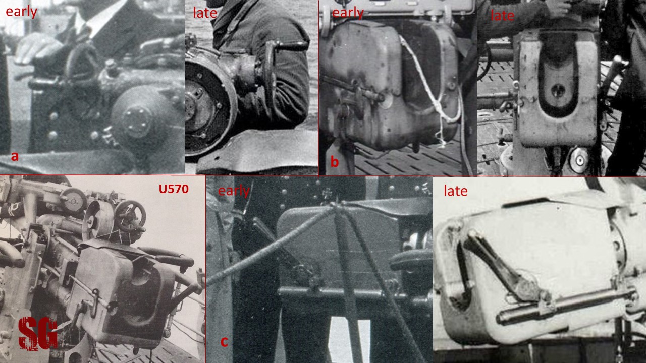
During the photographic study accompanying the build I was able to identify different variants of the main details i dealt with (below). a)Deflection block flywheel. Early type: three rays protruding posteriorly, late type: flat appearance. Same arrangement of the rays, knob and “curtain” aspect of the wheel profile opposite to the knob for both the variants. Occasionally a saucer-like flywheel (no rays) resembling the flywheel for the deflection setting dial arm was observed. b) Lower profile of the breech housingafter portion: concave (early) versus flat look (late). c) Breech block lever: longer/thinner (early) vs shorter/larger (late) look. U 570 gun (below) sported all three early details analyzed.
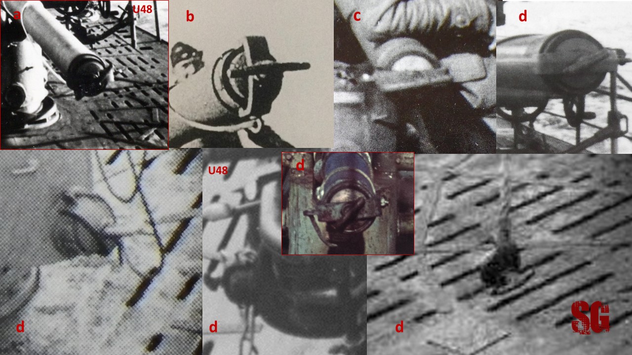
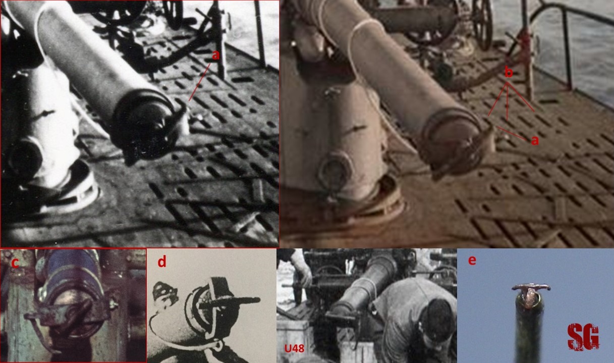
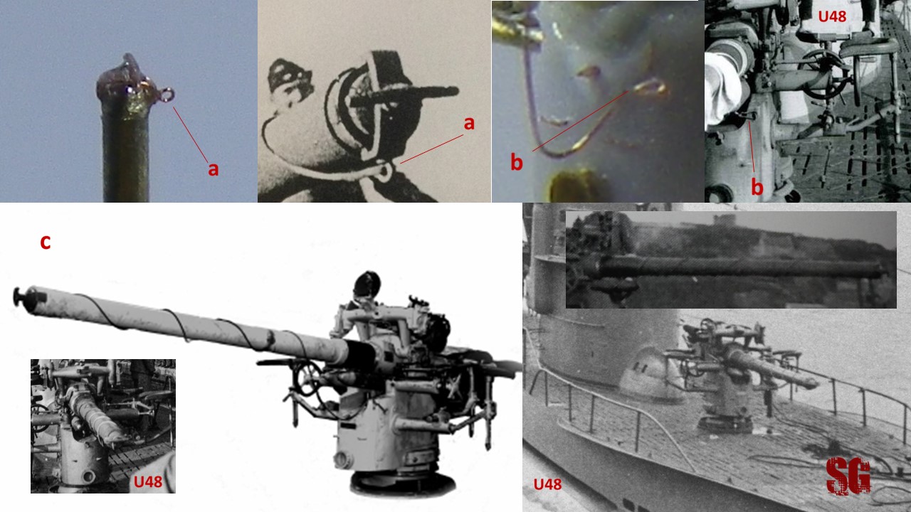
The muzzle cap was a chapter per se. I identified at least three variants of it, U 48 was equipped with an early version of the cap, just like the one of U46 shown in the pic (below, top left), at least until U 48 eight war patrol. This is the best picture I found to illustrate the details of this type of tampion, all the elements are perfectly visible. The cap consisted of a hemispheric main body(a) plugging the muzzle, protruding to some extent from it plus a locking fairing (b) on top of it, that locked at the muzzle recessed rim (d), providing watertightness. The locking handle (c) on top of the fairing had different looks and shapes. U 48 early variant of locking-handle followed the fairing profile bending posteriorly. It occasionally served as a coat hanger for the boat barber’s jacket 🙂 . I recreated the 0.13mm recessed rim at the muzzle (d) incising the muzzle outer profile with a needle and then diamond-filing the rim to the wanted depth while rotating the barrel (I havent got a lathe, so I took on the role of the slow-round-human-lathe for the occasion ). The 0.2 barrel lumen at the muzzle was enlarged to 0.25mm with a drill bit and a 0.25mm solder sphere (f)(a propos, a thousand thanks for the delivery and kind present Tigre! This is an official tribute) was positioned at the muzzle, protruding just the right tenths of a mm and was glued with CA. The locking fairing (b) was shaped out of a 0.1mm-large x 0.05mm-thick, flattened section of copper wire and glued on top of the solder ball. Finally, the locking handle(c) made of 0.03-ish mm copper wire reduced from 0.05 mm wire through sanding (yes, that infamous rolling technique ) was added. I chose to give the handle a different axis from the one of the locking fairing to make it more visible. All that work was insanely difficult but it was worth the effort. The ring for the muzzle cap line(e) placed on the fairing side will be added at a later stage, once the line is added. The line should be 0.03 mm thick, several tries to reproduce the line with 0.03mm copper wire obtained from reduction failed. The metal loses its properties and often breaks instead of bending. This is the biggest limit of the technique which works better for creating small straight sections that can be bent to some extent rather than a long twisting line. I am currently waiting for the delivery of an order of copper wires ranging from 0.01 mm to 0.04 mm (yes they exist, it was like discovering a new galaxy) that should open a wide range of new possibilities. December. We’ll see.
Curiosity: I identified at least three main variants of muzzle cap (below, a, b, d) and an oddity (c). U46 early variant (a). The caption U48 is wrong, I can now say it’s U 46. For a while the identity of the boat was uncertain, the possibile candidates were U 48 and U 46. Now it’s certain that the boat is U 46, photographed at Saint Nazaire. Anyway, you already know the details of this type of tampion. Not often seen, i guess the guns equipping U 48 sister boats (namely U 46 and U 47 and those VII B boats of that same Kiel batch) might have been sporting this variant of muzzle cap too. Standard early variant (b): long locking handle not protruding over the sides. Unusual variant (c): probably a (b) variant pictured in in a lo-res/blurred-at-the-muzzle shot, dunno. Standard late variant (d): shorter locking handle. The most frequently seen variant of the muzzle cap. Bottom row: late muzzle caps in their housing on the C/35 mount; middle pic: U 48 gun in action during the 9th war patrol, note the switch to the standard late variant. Bottom right picture, the dangling cap with only the locking handle attached, the locking fairing gone awol.
Errata Corrige (December 2021).After seeing the recently-published colourized version of the b/w pic showing U 46 gun muzzle (below, top left and right) on the Facebook page ” Das U-boot in farbe” (highly recommended), I realized how much I had misinterpreted it. Comparing the two pictures i realized that i had mistaken one of the deck’s drain holes (b) for the (non-existent) lateral section of the locking handle (a). In the b/w picture the images sum-up looking like a single element. In fact, the locking handle only had a minimal lateral extension or none at all, and that makes sense: if the lateral branches were as long as i had originally thought, turning the handle would have been impossible due to the presence of the ring for the securing line. So dumb of me. Therefore, I can now say with good approximation that only two versions of the handle existed: an early, long type (d), and a late shorter one (c). A recently-acquired U 48 picture confirms the new finding and I decided to modify the locking handle that I had already crafted accordingly (e): the handle was detached, cleaned of the CA residuals, its lateral extensions were trimmed and was finally re-glued (easier said than done ).
Finally, i completed the superdetailing of the foldable mount for the lead sight with some more thin plastic wire. Titanic effort but worth the effort. Now it looks more convincing. The usual comparison of the subassembly to my index finger. I hope you enjoy the progress of my work as much as i do.
Subassembly 3: pedestal (November 2021)
Not many modelling sessions in November. However, I managed to complete the gun pedestal. New photographic evidence (see my thread on the AMP forum for details https://models.rokket.biz/index.php?topic=858.30) showed that the pedestal holes (c,d) were located at 180 degrees from each other, they just sat at the opposite sides of the pedestal circumference. So, their actual and correct location is: starboard side 4hr and port side 10hr. Comparison with b/w pictures of the U48 gun confirmed the finding. (Technical drawings to your benefit 🙂 )
Once restated my assumptions it was time to correct the holes position on the pedestal: I filled the incorrectly located hole with epoxy putty and drilled another 0,15mm hole opposite to the previously-made one. Then the plastic ring was glued with CA to the combo Mirage Hobby PE- Albion Alloys tubing section (0.9mm diam x 0.6 mm tall) and more epoxy putty was applied to fill the gap between plastic roundel and PE. The pedestal was then sanded and given its sloping shape (a) turning the pedestal on its longitudinal axis while sanding. It took time and more than a modelling session was necessary to get the desired shape. The toothed fairing was then added (b) and glued with CA at every tooth. CA was also used as a filler to compensate for shorter teeth, the result was rewarding. I crafted a new disc from 0.02mm brass shim (1.5mm diam, central hole: 0.9 mm) (c) with a punch and die set, and glued it to the pedestal. The new disk was preferred to the 0.05mm-thick aluminium disk that I had prepared in 2016 because of its lesser thickness, that proved to be far more convincing. Finally I added a 0.1mm-tall spacing roundel made with a brass PE railing section on top of the disk. The final look of the pedestal, port (e) and starboard side (d).
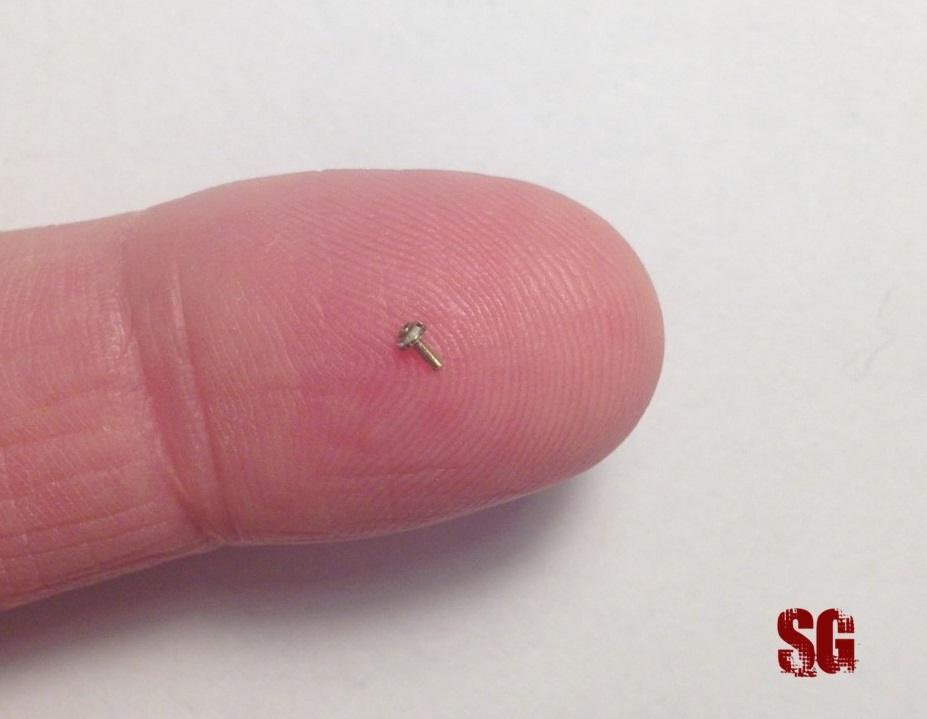
and the usual comparison with my index finger:
Another step forward, plus the pedestal is pretty convincing. Am happy!
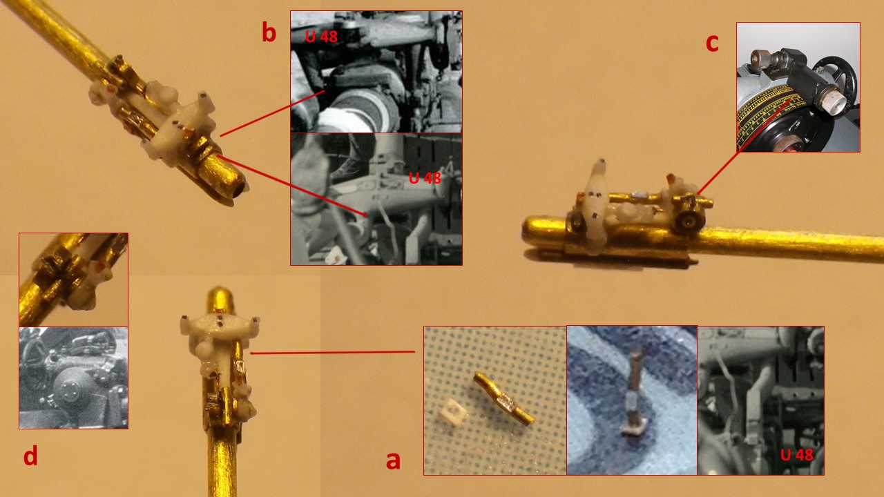
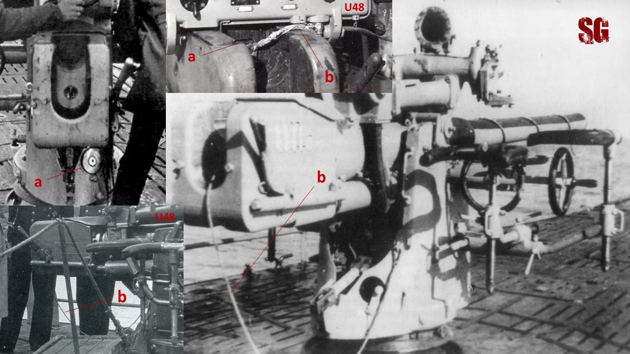
Subassembly 4: superdetailed mount and upper arms (December 2021-June 2022)
It took me six months to complete the C/35 mount. Nothing was easy or straightforward 🙂 . The work started with reducing the mount width scaling it down to 1.3 mm, which was much more appropriate than before. The lateral pillars hosting the pintle were thinned down through sanding and reshaped. In the process, one of the pillars detached several times and was reglued, the resulting gap was filled and sanded flat again and again. Time consuming. Research showed the presence of a gap between the upper arms and the pillars (below, a). The gap was carved out and refined. The holes originally meant for hosting the upper arms (see the mount paragraph previously posted) had to be sacrificed and new housing recesses were shaped de novo. A 0.3mm stainless steel needle acting as a pivot(n) was glued to the bottom surface allowing to manipulate the mount. The pivot is centered as the technical drawings suggested and will be crucial to link the mount to the pedestal at a later stage. A 1.4 mm long section of 0.4 diam brass tube was flattened on top and bottom surfaces and added to the mount to host the lower lateral arms and simulate their housing (b). Its protruding edges were sanded bilaterally to achieve a look similar to the real one. The aft fairing hole that housed the breech plug(m) was resized to 0.25 mm and the fairing details were crafted and added: the tiny arms to reel the breech plug line and the half ring that was meant to secure the line are small sections of 0.01 mm copper wire (c, d). The lock for the breech plug housing(f) is a small section of 0.01 mm copper wire flattended with pliers. The fairing mount (e) for the retractable arm supporting the after portion of the gun tube was shaped from a 0.13 mm styrene sheet and glued with CA. Then the 3 components of the arm were assembled w CA: the main shaft(g) is a section of 0.13 mm nickel wire; the (port) lateral locking lever(i) is a section of 0.08mm wire flattened to 0.05-ish mm; the after element(h) was made with the same flattened wire bent on itself and trimmed. The rectangular base with the pivoting T-branch of the arm (k) was crafted and assembled as shown in the sketch and then added to the mount.
The pintle (below, 1a) is a 0.3 mm diam disk made from 0.01 mm alu foil. Building a dedicated “home-made punch-and-die set” (1b) from styrene sheets and drill bits, allowed to obtain perfect tiny rounds. It worked just fine. The 0.3 mm-long handles (2c) adorning the after surface of the mount pillars were created with the help of a jig(2d) from 0.02 mm copper wire and added. Had to re-do the upper arms(3e) from 0.3 mm brass tubing because the previously-crafted arms broke when i decided to trim the 0.1mm wire that was soldered to them. The new arms were glued with CA. Since my gluing skills improved over the years i felt self-confident enough to try, it worked. The upper arms top and bottom surfaces were diamond-filed flat and their superstructures (3d) were assembled as shown in the sketch (3g). Each Superstructure was glued to the corresponding arm (f) and then laboriously sanded in situ until the desired shape was obtained (easy huh? )
The upper arms were then glued to the mount with the help of small blobs of blu-tack, that helped to keep position and alignement, given the minimal contact surface between arms and mount. CA once again made the miracle. Separating Blu-tack from the mount after gluing the arms was a miserable task, the blue sticky fellow got really affectionate to the mount and didn’t want to leave . Starboard side details were added: the rounded-edged element on top of the pillar(below, a) comes from an “inverted-L” section of bent 0.08mm copper wire. The bent wire was flattened on one branch only, and then trimmed-to-size and glued. The arm connecting the pintle to the upper arm superstructure(b) is a section of 0.06mm Shelf Oddity nickel wire. Its forward end inserts onto the top of the superstructure’s medial pillar. The brass traversing (d) and elevation (c) control flywheels are a gift from my friend Marek Targowicz at Shelf Oddity. He masterfully designed them for me and PE’d them on a 0.1 mm brass shim. I diamond-filed them to 0.08-ish mm and sanded-round their edges to some extent to improve their already excellent look. The wheels were designed with a central hole for their 0.1 mm connecting arm. Assembling them was straightforward and spared me a lot of time. The flywheels only lacked their 0.2mm handles, that were crafted from that plastic ribbon wire you know already and then glued. The gift from Marek came in a difficult time for me (i was undergoing chemotherapy. Yes. Now you know), it’s a touching gesture of friendship i will never forget. Marek flywheels were preferred to the ones i had scratchbuilt in 2015. They now sit perfectly on the mount honoring their designer and most of all honoring friendship (the elevation flywheels are only dry-fitted at the moment, to allow working on the lower lateral arms area at a later stage). The starboard elements of the aft fairing look sufficiently convincing when compared to the original pictures shot from a distance (e).
Port side details (below): The arm connecting the pintle to the upper arm superstructure (0.06 mm SO nickel wire) inserts underneath the superstructure’s medial pillar (a). The upper element semi-circular detail(b) comes from a section of a 0.3 mm diam ring made with 0.04mm brass wire, flattened and trimmed to the desired size. The lever allowing the gun to traverse(c) comes from a bent section of 0.06 mm SO wire. Discovering what was the function of the lever came from the sudy of many pictures and was confirmed by the always kind and qualified Mr Kai Steenbuck from the Cuxhaven U-Boot Museum ( https://uboot-recherche.de/en/ ) to whom am very grateful. When the lever is shifted forward (d), the mount is free to traverse; when it points backwards the mount is locked (c), as explained by a plaque which was located just above the lever (e). Take into account this finding in case you are considering to build a model showing the manned gun in action or simply traversing during the torpedo reloading.
Fore details (below): the housing for the muzzle cap is a section of 0.4 mm Albion Alloys brass tubing (a). Its lumen was enlarged with a drill bit to reduce the tube wall thickness and make it look more realistic. The tiny arms to reel the muzzle cap line(b) and the half ring that secured the line to the mount (c) are small sections of 0.01 mm copper wire. The butterflybolt(d) securing the frontal cover of the mount comes from 0.01mm bent and flattened copper wire. The asymmetric look of the upper arms superstructures was somehow respected (e).
Curiosities (below): the photographic research accompanying the build allowed me to identify different styles of the main details adorning the mount. 1) Pillars top elements: early version, rounded edges(1a) vs later sharp edges(1c). Pillar handles: early short version (1b) vs later/standard and longer version(1d). The short version sits higher than the longer version and has a less squared appearance. 2) Upper lateral arms superstructures: asymmetric/earlyconfiguration(2a) and mostly seen in pictures. The starboard arm superstructure sits lower than the contralateral; symmetric/late configuration (2b): both superstructures have the same height. 3) locking lever for the foldable arm supporting the after portion of gun tube. Early/standard configuration mostly seen in pictures: portside location of lever(3a). Late configuration, seldom seen: starboard side-located lever (3b). 4) The pillar top elements had different shapes given the sides. The port side showed an additional semicircular posterior element (4a) that is missing on the opposite side (4b). The arms connecting each pintle to its relative upper arm superstructure had a different forward insertion to the superstructure. Port side: the arm inserts beneath the superstructure’s medial pillar (4c). Starboard side: the arm inserts above the superstructure’s medial pillar (4d). The arms could also have different styles(d vs e). There was a plaque on the fore surface of the mount(5a) between the butterly bolt and the tiny arms for reeling the muzzle cap line. The writing on the plaque referring to the butterfly bolt and front cover said: “behelmierung der getriebe deckel offnen” (5a). Sometimes the plaque was overpainted with grey or detached with use and missing, just like in the case of U48’s (5b).
Closeup of the fore butterfly bolt (below, a) and how i managed to recreate it (a,b,c, am very proud of the achievement 🙂 ), plus the usual comparison picture.
Working on the mount was exhausting, it was difficult and kinda extreme for me. Dealing with such tiny measures, trying to figure out valid assembling strategies, adding all the details the mount was composed of and achieve a convincing look was nevertheless exciting. A real challenge. I hope you enjoyed the progress. To the next update!
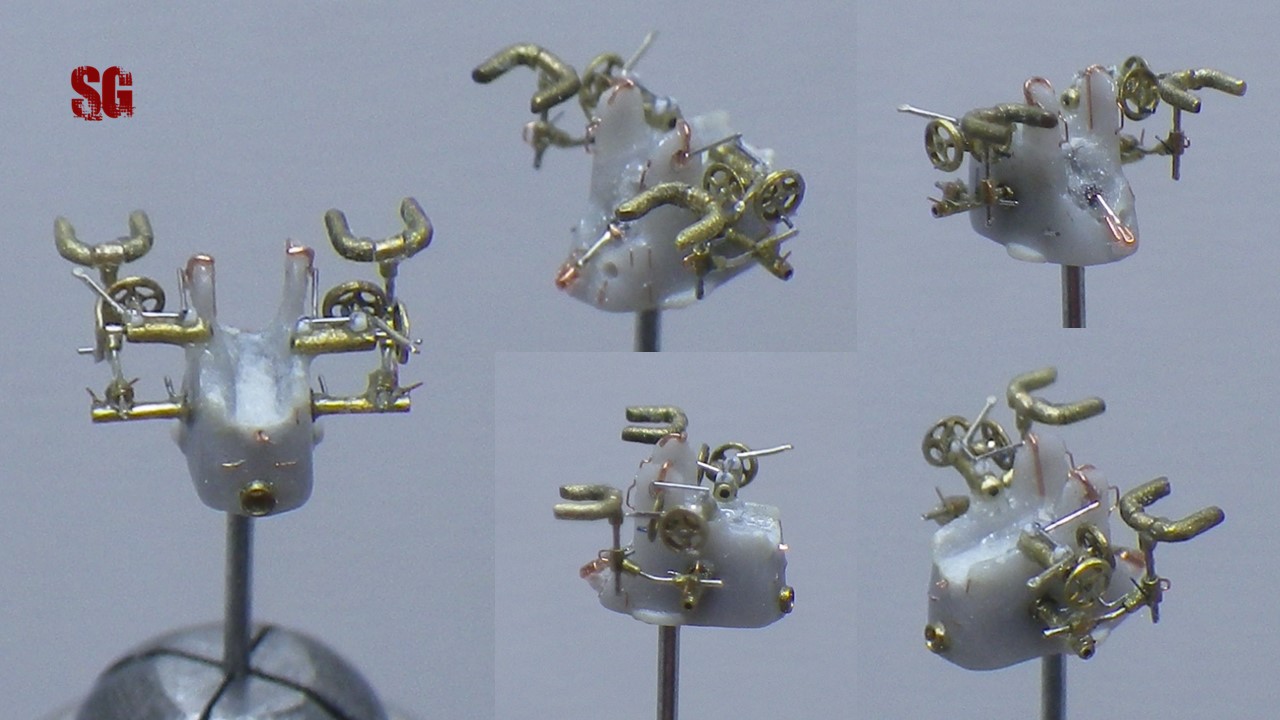
Subassembly 5: lower arms and safety harnesses(June 2022-March 2023)
Probably the most demanding part of the build. It took me 9 months to complete lower arms, safety harnesses and their sloping connecting arms and to superdetail them, with an average of 2 modelling sessions per week and plenty of intervals between the sessions. I re-did the lower arms using the now available 0.2 mm brass tubing. CA-gluing was preferred to micro-soldering to speed-up the building process. The cons of it are easily imaginable: the tiny contact surfaces and the minimal amounts of glue holding together the parts more than once proved unreliable, wrecking havoc during manipulation as you will read later. The main components of the arms were assembled paying attention that the 0.3 mm-tall transverse section (a) protruded 0.1 mm from the after edge of the arm. I carefully tried to avoid clogging with glue the tubes’ lumen that would later host the arms for the safety harnesses. The main details were therefore added: the proximal bars(b) were crafted from L-shaped sections of Shelf Oddity 0.6 mm wire with the touching branch flattened. The small adjusting handles on the after edge of main arm (c) and on top of the transverse section (d) are 0.3 mm sections of 0.02 mm copper wire. The decision to use 0.02 copper wire wasn’t a happy one since the flimsy handles bent in more than one occasion thereafter. The difficult-to-handle lower arms were eventually secured to the mount with a sigh of relief .
Re-did the 60°-angled lambda joints with 0.3 mm-tall x 0.2 mm brass tubing sections: luckily, ordinary cutter blades have a 60°-sloping and this feature was most useful allowing an easy cutting of the angled tubing sections and a quick assembly of “the lambdas” (below, top left). Elevation and traversing harnesses arms differ for the length of their sloping sections before the bending: the traversing arms sported a very short length of the sloping section (c), the elevation arms a much longer one (d). The lambda joints were superdetailed with their adjusting handles (b, this time i opted for a 0.3 mm-long section of 0.02 mm-10/0 ophtalmic nylon suture wire, unbendable) and the early stylesquared eyelets(a), crafted from 0.02mm copper wire, shaped with a dedicated micro-jig prepared for the purpose and cut. Gluing was not easy. A matter of trial and error. The tiny details were positioned on the lambdas with a CA debonder-moistened 5/0 brush (by the way, I use Glue Buster debonder and it works just fine, doesn’t melt styrene nor nylon, water consistency, perfect) and then glued by means of a 0.03 mm copper wire glue-applicator.
The harnesses components were finally assembled x 4 : 2015-built harnesses (a) + 0.2x 0.2 mm tubing (b) + 0.1 mm nickel wire sections (c). They were assembled to their corresponding arm (d) and each harness height was adjusted and fixed with a droplet of CA. Same way as for the real harnesses. This allowed to compensate for the minimal height discrepancies of the mount sides and reach a bilaterally-even/convincing result. The assembly of the completed traversing harnesses + sloping arms to the low lateral arms was disastrous: the starboard mount pillar handle (g) and the pintle arm (h) detached and pinged-off. They had to be redone and re-attached (one-week work). The transverse sections of the low arms detached too and the gluing proved to be a nearly impossible task. The damage was eventually fixed but the initial, nearly-reached perfection was lost forever. Well well.. Small nylon adjusting handles were added to the port side of both the lambdas (e, f), same way as for the real thing.
The elevation harnesses were mounted onto their corresponding lambda arms and test-fitted to each lower arm. Height was adjusted and secured w CA. Then they were completed with their nylon adjusting handles (b, d) and dismounted. Laborious and risky work. Note how the real starboard arms handles faced forward (b) and the port ones faced aft (d). The elevation arms will be glued to the gun mount at a later stage to allow a more comfortable assembly of the gun tube to the mount. The usual comparison with my index finger shows the actual dimensions of the harnesses.
The upper arms oblique levers (below) were the triggers to fire the gun, as always-precious Mr Kai Steenbuck from the Deutsches U-boot Museum kindly informed me of. They were crafted from 0.8 -ish sections of 0.1 Albion Alloys nickel wire whose proximal extremities were cut to a 60° angle and distal ends flattened/shaped with sandpaped to resemble the round flat knob of the real levers. Mounting the port handle was straightforward. The assembling process of the starboard lever was instead once again, disastrous. The upper arm with the flywheels and other details detached from the gun mount and had to be reglued. Madness, once again. Eventually fixed but not as perfect as it used to be. Live and let live . Adding each new component to the already-assembled mount proves to be more and more difficult, subassemblies and details tend to detach due to the minimal amount of glue holding them together. It’s just like adding a new card to a house of cards: difficult, time consuming, potentially catastrophic and most stressful. Note the different direction the two levers had: the starboard one pointed aft (c) and the port one pointed forward (d). A highly-contrasted picture enhances the result obtained that am really proud of.
Curiosities. As usual, the in-depth photographic study of the gun components brought me to notice oddities and different styles. First of all the location of the adjusting handles (top row, left). Elevation harnesses arms adjusting handles: starboard one located forward (unnamed arrow ), port one pointing aft (b). Lower arms adjusting handles: after side of each main arm (e) and top of each transverse section (f). The traversing harnesses armsadjusting handles were located on the port side of each arm (c, d). “Lambda joints” squared eyelets: early (right/top and right/central pics) eyelets sat higher than their late counterparts (top row, central picture). The upper arms oblique levers (g) were an early feature. They had a very important purpose, as they were the triggers to fire the gun. They branched with a 60° angle from the main axis of the upper arm. The starboard leverpointed aft while the port one pointed forward. I identified a different, apparently late variant of it made of a crank (h) pointing forward and a lateral L-shaped lever extending aft (i) (which was probably the late version of the trigger). This variant equipped famous boats such as U 96, U 552, U 73 and U 203.
The actual state of the mount, after several accident repairs, sporting the lower arms with the fully-detailed traversing harnesses. Far from perfect but landing on its feet. A miracle. Baroque isn’t it?
To the next update!
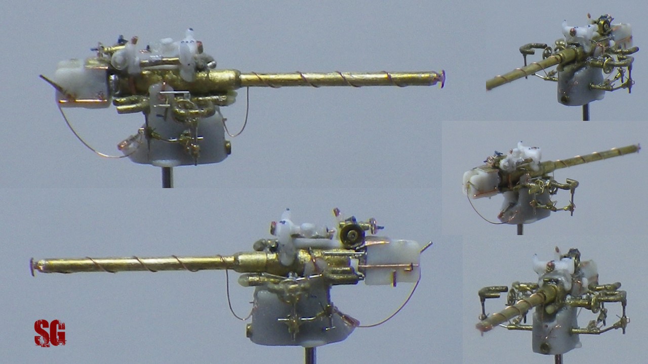
Gun completed!(March 2023)
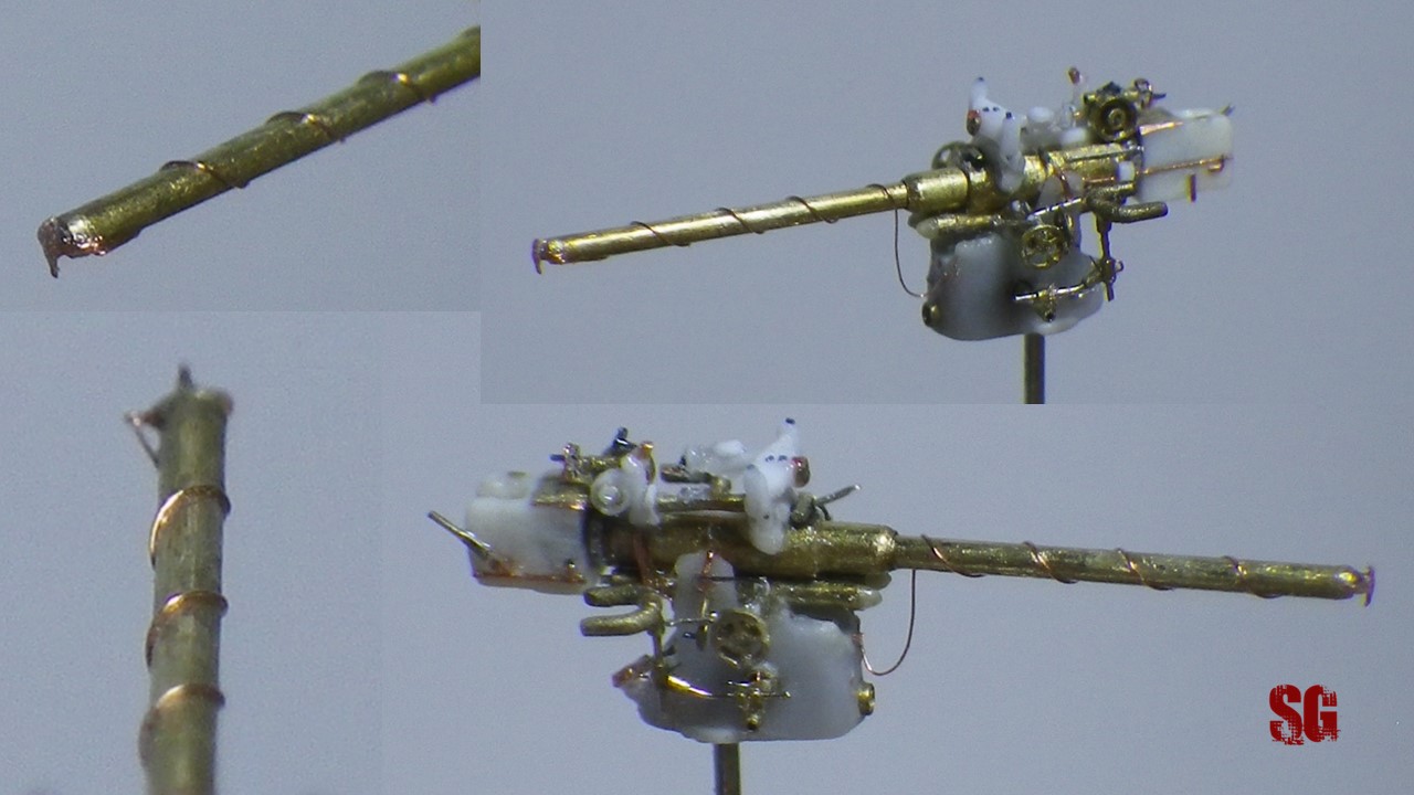
The final steps of the assembly weren’t free from contingencies. The initial, big step was gluing the gun tube to the mount. The first attempt was catastrophic. I glued the gun tube too far back on the mount and secured it with a generous quantity of CA. I realized my mistake only the morning after and was forced to unglue the subassemblies with debonder and reposition the gun tube correctly. As a consequence, the port pillar of the mount with the connected pintle arm broke, the upper arm detached and the elevation flywheel went awol, losing its handle in the process of leaving.Aaargh!. The repairing process was slow and tricky, especially replacing the pintle arm and repairing the broken pillar, which was then glued directly onto the now-in-place-gun tube. Try to imagine how difficult it was to fill and sand the resulting seam on the mount with all the details already in situ. I therefore added the last two details, the small transverse bars (0.06 mm Shelf Oddity wire) running on top of the proximal part of the gun tube, connecting to the mount pillars superstructures. Once replaced the missing details it was time to superdetail the barrel with the line for the muzzle cap. A 0.06 mm diameter muzzle cap ring(a) was crafted from 0.03 mm copper wire and glued to the side of the locking fairing. Then a snap-hook for the mount-end of the cable (b) was shaped from 0.01 mm copper wire and added. Photographic research showed (below, bottom row) that well-rigged out barrels had muzzle lines coiled with an average of 4 spires either in a clockwise or an anti-clockwise fashion (from muzzle to mount), depending on the position of the muzzle ring (c). I chose a 4 spires-style coiled clockwise and a port-located ring configuration, just like what can be figured-out in the bottom right U 48 picture below.
0.02 mm copper wire was used to simulate the line. It was glued to the barrel progressively, starting from the muzzle ring on, in a backwards fashion. Care was given not to cause any sharp bending of the wire that would look unnatural. The superdetailed barrel was then added to the gun and the redundant muzzle line trimmed. I tried to simulate the effect of gravity on the cable by shaping the loop next to the mount with the tapered tip of a toothpick, after the proximal end of the wire had been secured to the mount. The result is pretty convincing (below).
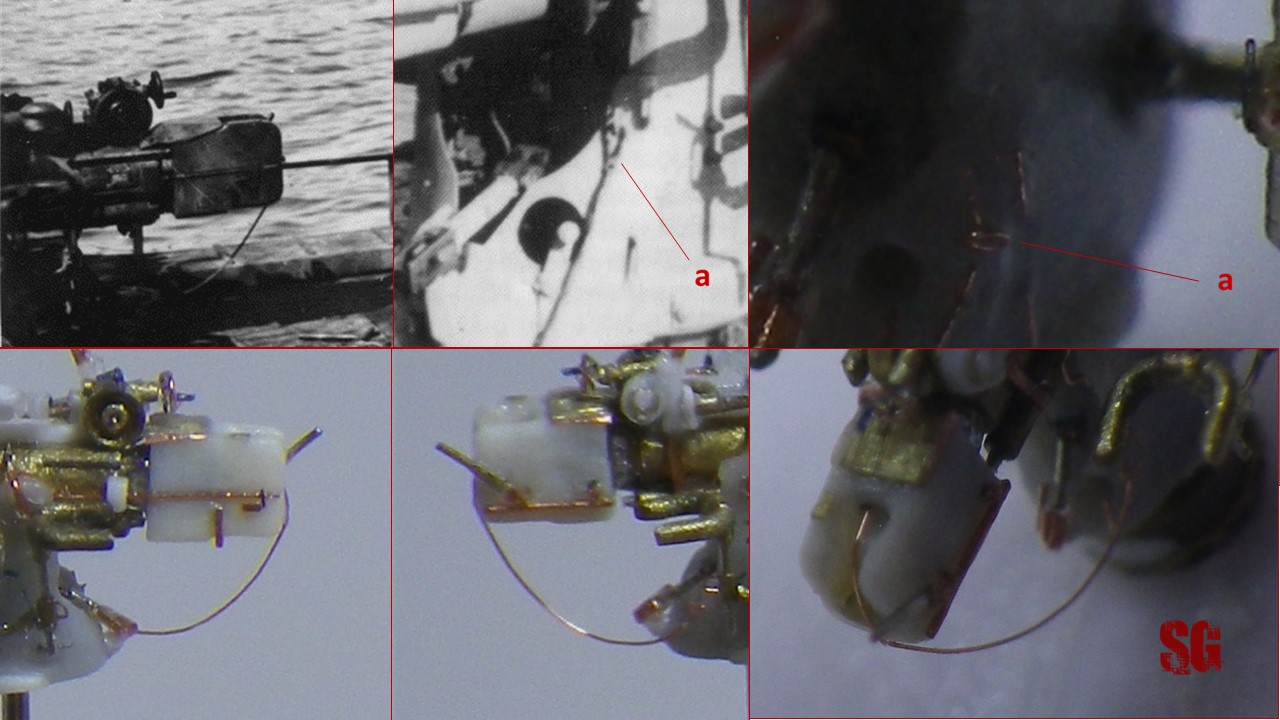
Many modellers seem to ignore the fact that U-boat guns sported another line (b) connecting the mount to the breech block, meant to secure the breech plug (a). When the gun was in action the plug was removed from the breech and stored in a dedicated housing hole located on the starboard side of the mount’s posterior fairing. Adding the breech plug line to your model will result in a much improved accuracy and realism. I’ve chosen the style pictured below for my project: a simple loose loop bridging from mount to breech block.
Another almost-invisible (some 0.1-ish mm) snap-hook was crafted with 0,01 copper wire and added (below, a. Double-magnify the image to see it). Each end of the 0,02 mm copper wire line was glued. Then the cable was shaped in the usual fashion to achieve the desired look.
Next in turn was the addition of both the elevation safety harnesses. That was the final act of the build. Positioning and gluing the harnesses was uneventful this time and i could finally breathe a deep, long-lasting sigh of relief . Mission accomplished, at last.
I dry-fitted the gun to its pedestal, both will be kept separated until the final gluing to the submarine deck takes place, in order to facilitate the assembly. No worries, the gun is slightly leaning forward in the pictures due to the unstable/provisional dry-fitting. The completed gun is a splendid sight to my eyes. It sports every main detail the real gun sported. It’s the achievement of a project lasting nine years, a project that tested my nerves and stubbornness, that kept my mind alive in the dark days of chemotherapy and throughout these difficult last years. A source of unexpected learning and a good friend. Bottom left: the gun minus the elevation harnesses compared to the equivalent provided in the kit by Mirage Hobby. Now you understand the reason why I threw myself into this complicated project back then . There are four people i’d like to thank for their invaluable assistance and support: Dougie Martindale, Marek Targowicz, Mr Kai Steenbuck, EJ Foeth. I am lucky and honored that our paths have crossed. Special thanks to always-enthusiastic Tigre, number one fan of this project and supplier of many hardware materials .All my gratitude goes to Miroslaw Skwiot too, whose excellent “German Naval Guns 1939-1945” has proved fundamental in the making of this scratchbuilt little gun. Below right: time for savouring a very happy moment in my life.
The next modelling step will be working on the small SLC manned-torpedo side-project. Am eager to be back at work on it soon. Cheers.
Starting with the WEM PE as a base which acted as a template for the main body of the gun, I scratchbuilt the rest of the gun with 0.13mm styrene, stretched sprue (barrel, top of the gun’s main body and “phi-shaped” sight mount, barely visible in the pictures), 0.13mm copper wire and pieces of super-thin 1/700 PE railings from L’Arsenal. The 21 (!) pieces were assembled mainly w CA and there are also two micro-welds. I built the gun in 2011. I had decided to start my project with the most difficult parts of the kit (the 2cm and 8.8 gun) and to date am still stuck with them(!). I am sorry for I didn’t take WIP shots of the gun at the time as I hadn’t thought I would keep a photographic diary of my project back then. Enjoy the final result.
Below, “The Three Amigos” (from L to R): WEM PE, my AA gun and the one by Mirage Hobby.
As you probably noticed I omitted the muzzle brake since I think that the small scale (or should I say my dexterity?) doesn’t allow to reproduce it in a convincing way without hampering the final result. Fortunately there’s photographic evidence of operational use of C/30s without the muzzle brake. The picture below shows an MG C/30 operating without it: I am happy and in peace with my decision 🙂 .
Mirage Hobby1 400 –U 84VIIB German Submarine (Ref MIR40410)
A release from the early 2000s, the kit is very easy to build and a good base for superdetailing. The grey plastic responds well to carving, drilling, sanding and scribing. Main flaws: lack of detail. Torpedo doors missing, aft torpedo tube non-existent (not even the concavity in the hull), weld lines on saddletanks and lower hull missing. Turret details: minimal. 8.8 gun over-dimensioned (in common with the IX boat series also produced by Mirage-Hobby and thus looking more similar to the 10.5 cm than to the 8.8. 20 mm AA gun: awful. Decks: forget about them. Only one lateral air trunk provided (I keep asking myself why all the main brands keep on doing the same mistake, the lateral trunks were bilateral!). Pros: its small dimensions and correct looking-shape. Nice flooding holes pattern (some minor corrections needed). I apologise for the poor quality of the picture but don’t worry we’ll see the kit details one by one at each step of the building.
Aftermarket:
Mirage Hobby U-Boot VIIB submarine Photo-Etched set 1/400 (Ref MIR009-40410). To improve the U-boat plastic kits and kick them to a good level of detail, Mirage Hobby produced high quality PE frets for each of its type VII kits. At the time I bought mine they were sold separately from the plastic kits. Nowadays they are included in most of them. The PEs are wonderful, very thin and detailed: they really complete the plastic model, helping to achieve a very convincing final look. Only some minor flaws to be corrected.
Tom Modelworks produces dedicated PEs (Ref nr 4019) for all the main type VII versions produced by Mirage Hobby… and the good thing is that you get all the PEs needed for each variant (B, C turm 0, II and IV) in a single brass fret, which is inexpensive and a pretty good deal! A most clever idea. Although the quality is not as high as the PEs released by Mirage Hobby, they are a very nice complement to them since they also feature rudders and diving planes. For a great review about them go at: http://www.steelnavy.com/TomsTypeVII400.htm
L’Arsenal PE perforated catwalks (Ref AC 700 24): a real jewel. After searching and searching I came to the conclusion that the 1/700 catwalks are more suitable than their 1/400 brothers to fit the turret and wintergarden deck of a 1/400 U-boat model. The finesse of the pattern is unbeatable and there’s nothing else around better than them to reproduce the perforated catwalks used on U-boats turret decks: I have tried a wide range of micro-nets from the most different origins (steel and alloy micro-nets, plastic tea bags, plastic and canvas ribbons, aluminuim packagings with the most bizarre checkered patterns, etc) and none equals L’Arsenal 1/700 perforated catwalks. Masterpiece. I ordered mine directly at L’Arsenal website, together with many other 1/400 and 1/700 PE sets and railings from l’Arsenal and White Ensign Models to be used as source of materials for scratchbuilding. I must say that quality from both L’Arsenal and WEM is really high, details are great and the PEs are very well designed and thin. Also, L’Arsenal Staff is very kind and professional and the entire mailing order/shipping process is flawless. I wish to thank specifically Monsieur Jacques Druel at l’Arsenal for the kindness and savoire-faire shown on several occasions. An Outstanding Gentleman. All my gratitude to him.
WEM 1/400 Kriegsmarine anti-aircraft guns PE set (Ref WEM PE 4006). Top marks. Here’s a very nice review about them: http://www.steelnavy.com/WEM400GermanAA.htm . You’ll see how the 2 cm MG C/30 AA gun can be improved to a more realistic 3-D finish later on.

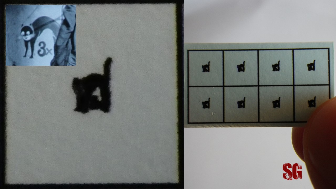
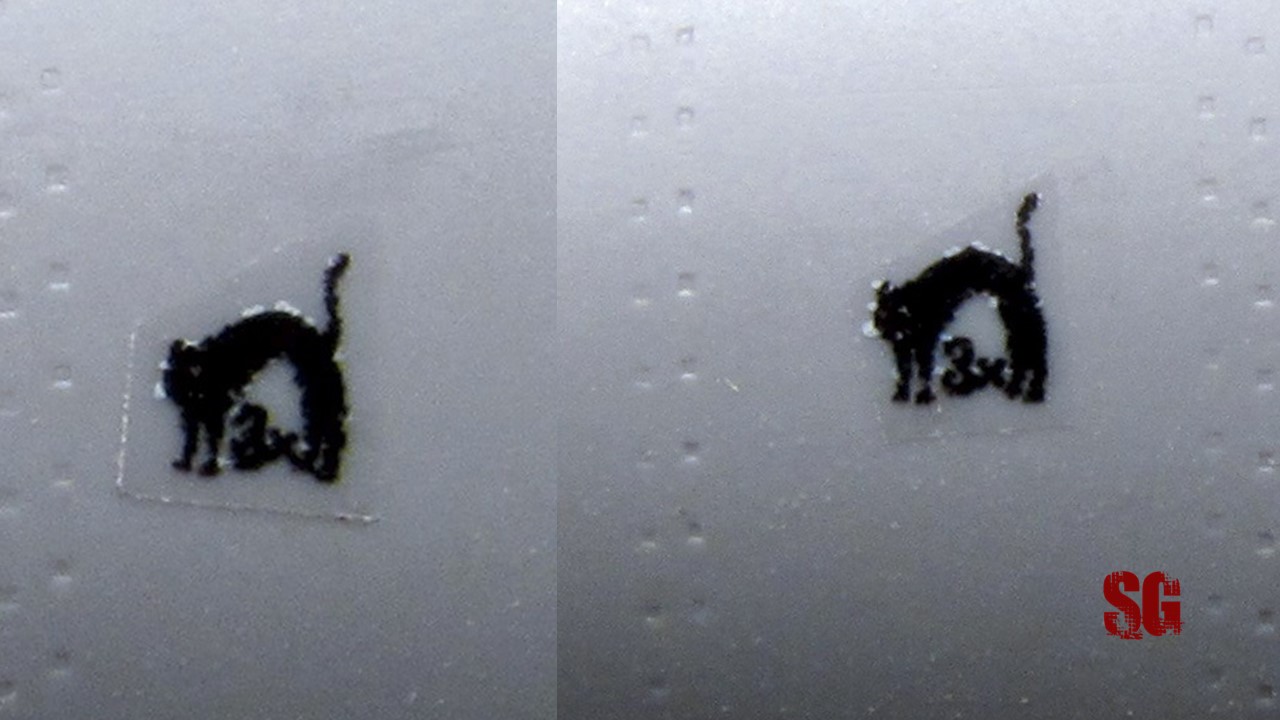
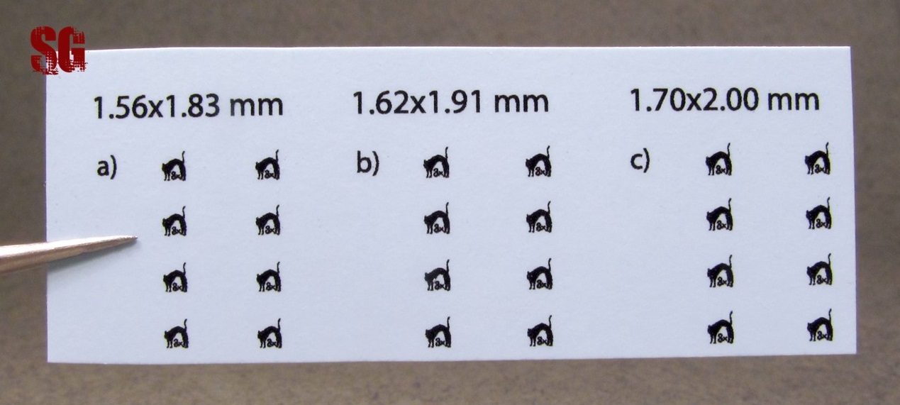


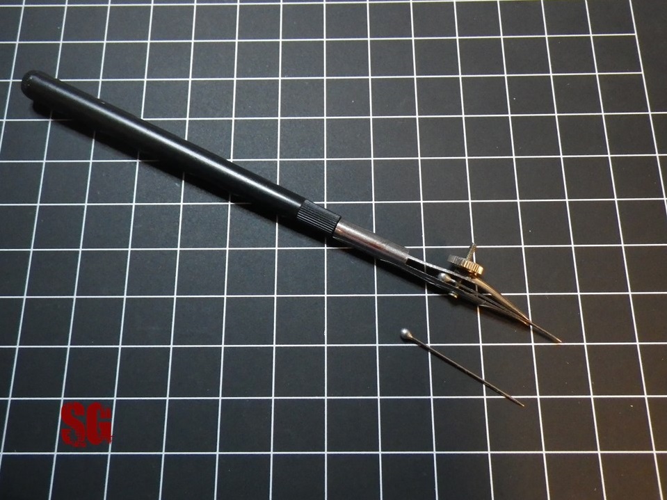
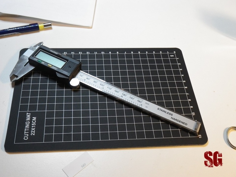
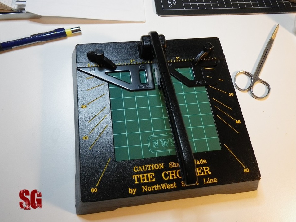
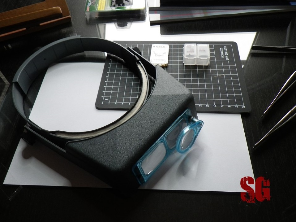


 : I will divide the build in 6 different sub-assemblies: gun mount, barrel, breech, recoil tray, superstructure, lateral arms.